This release brings changes to the core platform, 3D solid modeling, Mechanica, Construction, Raster and Topoplan. Choose a section below for the tools you use.
What’s new in nanoCAD Platform 23
Batch file processing
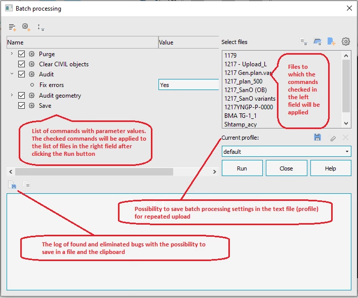
Run AUDIT and -PURGE across several drawings at once with the new batch utility. Use its dialog to choose the drawings, cleanup options and other processing settings.
Open the batch dialog with BATCHPROCESS.
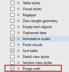
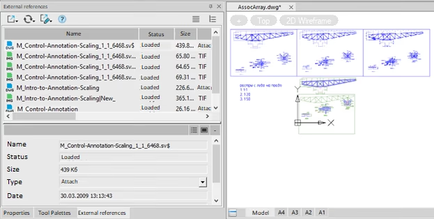
Batch-purging external references
Choose Purge xrefs to run -PURGE on externally referenced drawings as well as the host files.
For example, removing unwanted annotation scales from a host drawing can require purging every external reference that contains them.
The utility opens and purges the referenced files, then updates the references in the drawing.
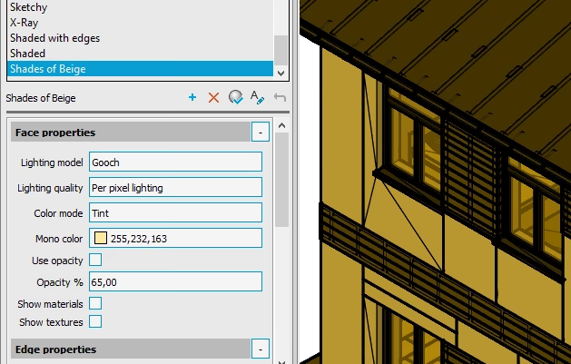
New visual styles
You can edit the new visual styles or create your own. Batch processing can also open and purge external references before updating them in the drawing.
- Conceptual — applies smooth shading with Gooch-style transitions from cool to warm colors. This emphasizes shape without relying on dark shadows.
- Realistic — displays materials on smoothly shaded objects.
- Wireframe — displays only lines and curves. Draw order and 2D solid fills are hidden. Changing the viewing direction does not require the geometry to be regenerated.
- Hidden — shows the wireframe but hides edges behind visible faces.
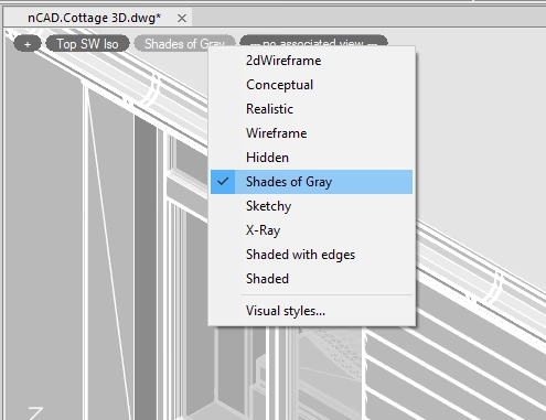
- Grayscale — displays objects in shades of gray.
- Sketchy — gives edges a freehand appearance using the Line Extend and Jitter modifiers.
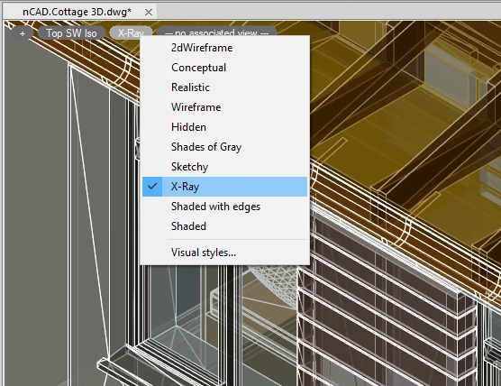
- X-ray - objects are partially transparent.
- Shaded with edges — smooth shading with visible edges.
- Shaded — displays objects with smooth shading.
Visual Style Manager
Use Visual Styles Manager (VISUALSTYLES) to create or edit styles. Apply one to the current viewport and preview the result as you work.
Materials Editor
Run MATBROWSEROPEN to open the Materials Browser and Material Editor.
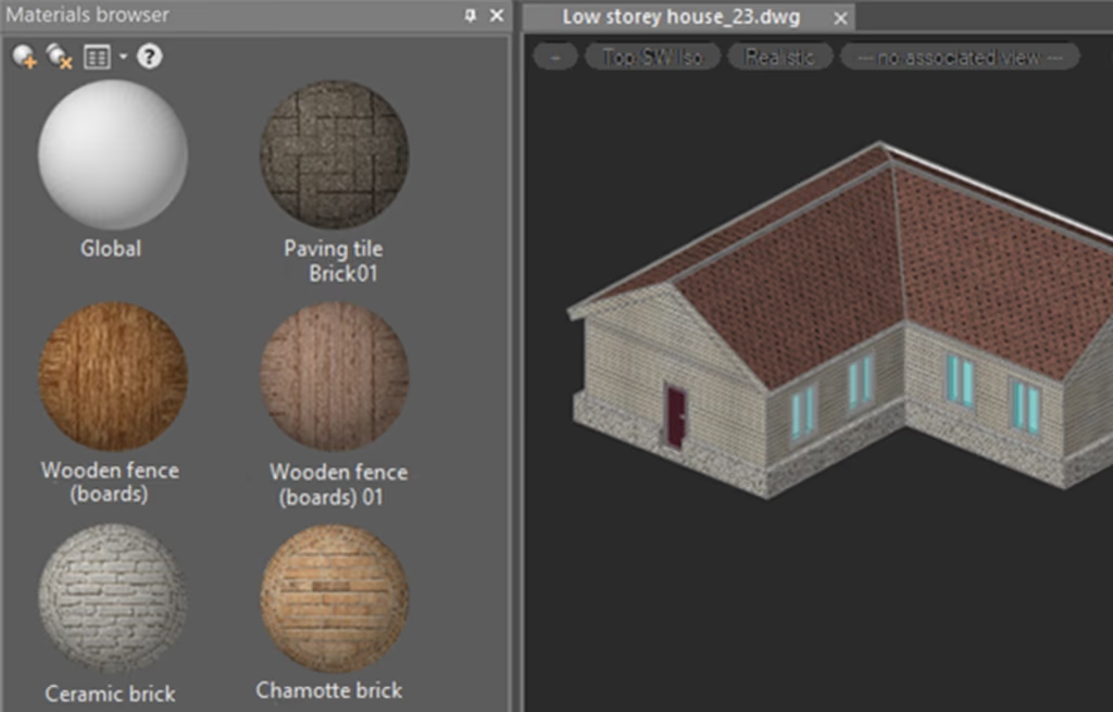
Materials library
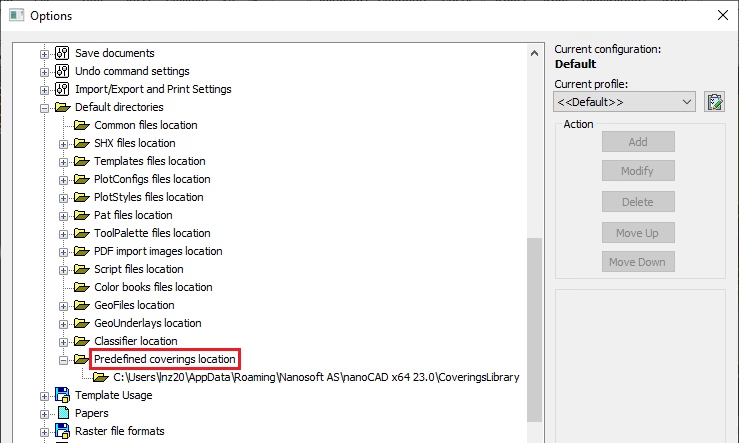
The installer now includes a materials library in the CoveringsLibrary folder under %APPDATA%\Nanosoft AS\nanoCAD x64 23.0. Change its location under Options → Standard directories, or add your own material libraries:
Applying materials to individual faces
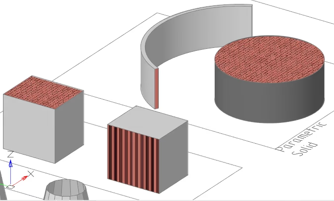
Hold Ctrl to select individual faces on one or more objects, then assign a material to those faces. Previously materials could be applied only to the whole object.
Creating and managing named views
Named views now store the visual style along with the camera position, layer visibility and freeze states, clipping prism settings and coordinate system position.
A named view can now display just a chosen set of objects. Applications can also reverse that behavior and use the set to specify which objects to hide.
The view API lets specialist applications display the same object differently in a plan, section or diagram.
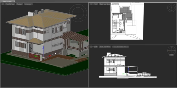
Checking viewports
When opening a drawing, nanoCAD now checks viewport data. If the check finds a problem, a dialog offers to repair it automatically.
Aligning viewports
ALIGNSPACE can now align a viewport to points specified in other viewports.
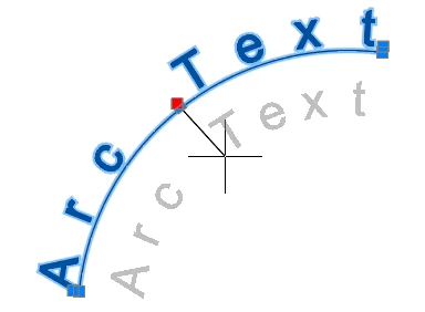
Arc-aligned text
Use ARCTEXT to place text along an arc. The text remains linked to the arc and adjusts its position and spacing when the arc’s length or curvature changes.
Drawing a rectangle from its center
RECTCENTER creates a rectangular polyline from its center and one corner.
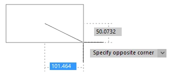
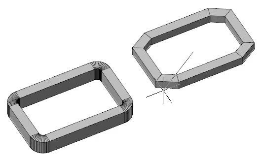
You can specify length, width, area, rotation angle, chamfer distance or corner radius.
Layer Options in Drawing Explorer
Drawing Explorer now displays layer properties including current layer, external-reference layer, on/off, frozen/thawed and layer color.
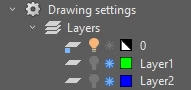
Ctrl-click a layer icon to change the corresponding setting. Double-click a layer to make it current.
Editing multiple multiline text objects
After editing one multiline text object, MTEXTEDIT (MTEDIT) prompts for another. Press Esc to finish.
Use the Mode option to control whether MTEXTEDIT repeats:
0 - Multiple. Enables automatic repetition of the MTEXTEDIT command.
1 — Single. MTEXTEDIT edits one text object at a time.

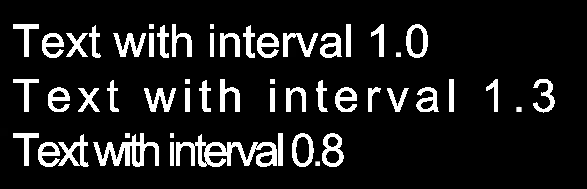
Text Character Spacing
The Tracking control in the multiline text editor adjusts character spacing.
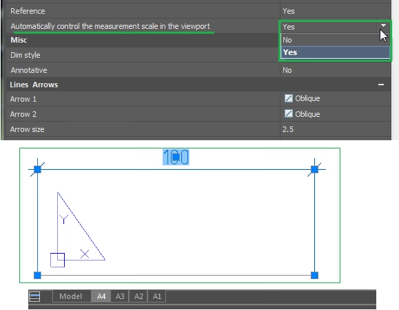
Automatic dimension scaling
A new property automatically sets the scale of dimensions in a viewport.
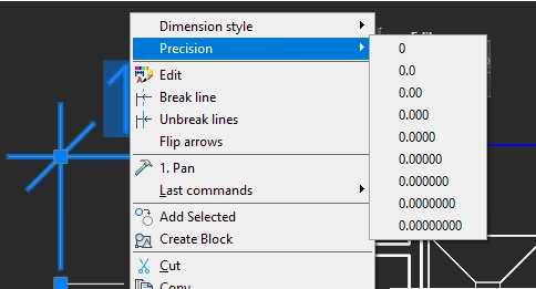
In the context menu of the selected dimension, you can now control its accuracy:
Copying hatch properties
Match Properties (MATCHPROP) now also copies a hatch’s background.
Aligning raster images
ALIGN now clears the image highlight so you can see the raster features as you pick alignment points.
Importing page settings for batch printing
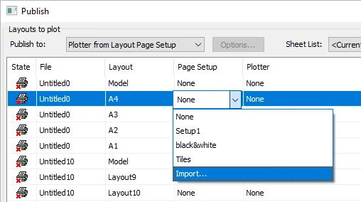
Batch Plot can now import page setups from DWG drawings, DWT templates, DXF files and DWS standards files.
Sorting in the Batch Plot window
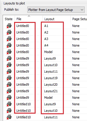
Batch Plot now sorts filenames and layout names numerically as well as alphabetically. For example, Layout 10 follows Layout 9 when sorting in ascending order.
Excluding layer information from PDF output
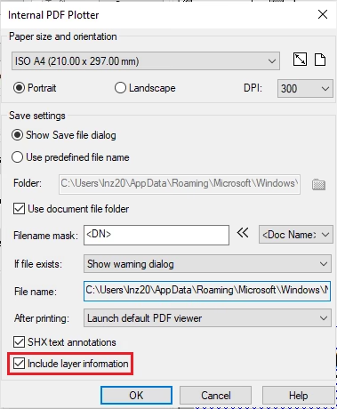
The internal PDF plotter now includes an Include layer information option. Clear it when you want a simpler PDF to work with downstream.
Delete Duplicate Objects when importing PDF
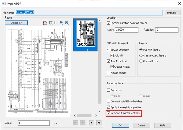
PDFIMPORT now offers Remove duplicate objects. Turn it off if you want to speed up the import.
Selection clipping prism
MCLIPBYSELECTION fits a clipping prism around the combined extents of the selected objects.
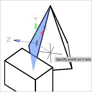
UCS per 3D object face
With Dynamic UCS enabled (F6), use the Face option of UCS to align the coordinate system to a face on a 3D object. Hover over a face to preview the new UCS.
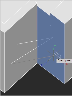
UCS when specifying a vertex
In earlier versions of nanoCAD, dynamic UCS mode allowed the UCS plane to be specified on the screen only once during the drawing/editing command's work (when requesting the first vertex). Later queries and drawings were made in the same UCS, until the end of the command.
To specify a new UCS plane at the next coordinate prompt, hold Ctrl + ~ while selecting the vertex.
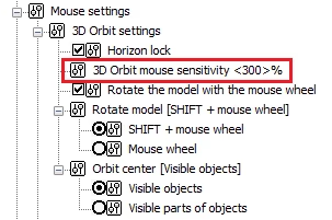
Rotation of the model with the mouse wheel
The settings for rotating the model with the mouse wheel in the Options dialog box have been redesigned and are now more understandable. You can disable or assign the rotation of the mouse wheel (with or without MAYUS) and set the rotation speed of the model.
Import of IFCs
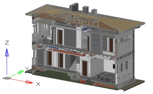
It is now possible to import large IFC files (1 GB or more). In addition, when importing an IFC file, IFC architectural objects are now automatically classified by layer.
Extension of polylines with smoothing
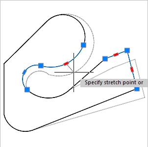
In the Dynamic Mode Extend command (LENGTHEN), polylines are lengthened/cut in one or both directions not only for extreme segments, but for the entire polyline. Dynamic mode is now also available for quadratic and cubic smoothing polylines.
Selection and editing of polyline segments
It is now possible to select individual segments of the Polyline object while holding down the CTRL key (or MAYUS+CTRL, depending on the selection mode).Selected segments have functional grips that can be used to edit them.
Snapping to spline knots and vertices in 3D
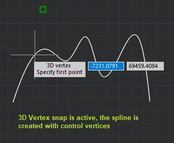
The 3D drawing fits to the Knot and Vertice spline. The 3D Knot Snap finds adjustment points in a spline created by adjustment points. The 3D Vertex Snap finds control vertices in a spline created from control vertices.
Create a document from the command line
The new QNEW command is designed to create a document from the command line without having to switch to the dialogless mode (FILEDIA=0).
Command-line version of ATTEXT
Scripts can now call -ATTEXT to extract attribute text to a file without opening a dialog.
Copying of Properties
Match Properties (MATCHPROP) can now copy viewport layer property overrides.
Command Options Select Group
A new Select Group button runs PGROUP.
The button changes the value of the PICKSTYLE variable to 0 or 1:
0 - No group selection, the object included in the group is selected;
1 - When selecting an object from a group, all the objects in the group are selected.
Selection dialog
A status bar control now manages the Selection dialog. When objects are close together or overlap, the dialog lets you choose which one to select.
Customizing the ribbon
Developers can now switch the contents of a ribbon tab without using system variables, much as the modeling-mode buttons change the 3D Tools tab. Dedicated commands define the content of each tab state.
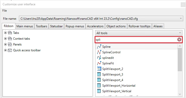
Improved search in the interface configuration window
Search in Customize User Interface (INTERFACE) now suggests matching commands as you type, just like the command line.
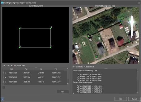
Map Insertion with Control Points
MAPVIEW can now align a raster map underlay using control points. Select matching points in the drawing and the map in the new dialog.
Insertion of multiple external references
You can now attach several DWG files as external references in a single operation.
Start DWG Reference and use Ctrl or Shift to select the DWG files. Set the insertion options and click OK to attach the files with those settings.
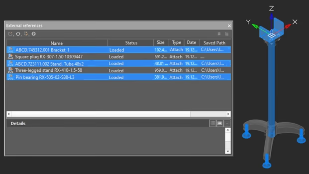
Highlight external references in a drawing
Now, the external references selected in the External References dialog box are automatically selected and highlighted in the drawing. Conversely, when selecting xref objects in a drawing, their names will be automatically selected in the External References dialog box. Single and multiple selection is supported (using CTRL and MAYUS)
New commands in the External References dialog box
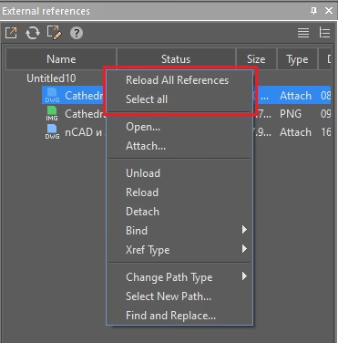
The External References context menu now includes Reload All References and Select All.
Multilingual text fixes
Fixed misplaced characters in Indic text and broken connections between Arabic letters. Arabic text now remains joined and legible in both the editor and the drawing.
Text and attribute fixes
When you edit a multiline attribute with EATTEDIT, the rest of the block remains visible under either ATTIPE setting (0 or 1). Multiline background masking now works in model space, and FIND can replace text as well as find it in multiline text.
PDF fixes
The internal PDF plotter now includes drawing views even when heading text extends beyond the view boundary.
PDFs plotted from DWG files with many objects now render faster in a PDF viewer.
Fixed a case where importing a PDF produced multiple copies of the same object.
Fixed errors and slowdowns when attaching several PDF underlays to a DWG.
Corrections in graphical display
Editing a multileader in an affected drawing no longer shifts its position.
Large raster images now display in full.
Fixed a problem that caused dimensions to shift inside a viewport.
Fixed drawing-specific errors that affected the display of objects and boundaries and broke associative links.
Object snap fixes
Quadrant snap now respects the UCS in which an arc or circle was drawn when that UCS is rotated relative to the WCS. For an ellipse, Quadrant works in both coordinate systems.
When drawing on the top face of a 3D solid, 2D object snaps no longer pick up unwanted points on the lower face.
Drawing fixes and improvements
When drawing an arc by center, start and angle, the angle is now measured from the specified start point.
Changing a region’s editing mode with its round grip now affects only that region, even if several objects are selected.
Fixed a case where window and crossing selections failed to select objects in a drawing.
Switching from paper space to model space no longer changes the measurement scale in an affected file.
Interoperability fixes for files from other CAD applications
Fixed a STEP save failure that reported ‘Empty ACIS not allowed: (63)’ and left the file unwritten.
Fixed compatibility issues affecting files recovered in version 20.1. Drawings created in versions 21.0 or 22.0 and saved in version 23 now open in other CAD programs without recovery.
Fixed a displaced multileader in a drawing with a UCS defined in another CAD program.
FILLET now accepts a zero radius in Trim mode.
The External Reference Manager now gives the Name and Status columns more room by default.
Printing fixes
Printing fixes cover the following devices:
HP Designjet T770
Konica Minolta bizhub C224e
HP Designjet T1100
IFC import fixes
Corrected missing faces and objects on IFC import, including walls with window openings in an IFC4 file.
Working with layers
LAYISO now remembers its settings across sessions. The Match Layer command (LAYMCH) works again.
Crash fixes
RCP point cloud import (NPC_IMPORT) no longer hangs on affected files larger than 2 GB. The importer now checks RCS files and generates file paths correctly.
Fixed a crash when selecting a DWG table in an affected drawing.
Fixed a crash when importing certain IFC files.
Fixed a crash when importing a PDF or inserting it as an underlay.
Fixes for specific drawings
Fixed a broken associative link that produced an error when editing dimensions in an affected drawing.
Fixed a crash in Construction and Mechanica when opening files with proxy objects.
Fixed an error when opening a file containing polygon faces that could not be tessellated correctly.
Fixed an error when opening a drawing containing problematic solid geometry.
Fixed an error when opening a drawing with damaged 3D geometry.
Working with point cloud databases
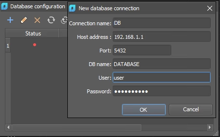
Use DB_TO_NPC to load a point cloud from the connected database into the drawing. If a connection has not yet been set up, the command prompts you to configure one.
You can preview the cloud and adjust import settings in the dialog before loading it from the database.
Displaying detected features in point clouds
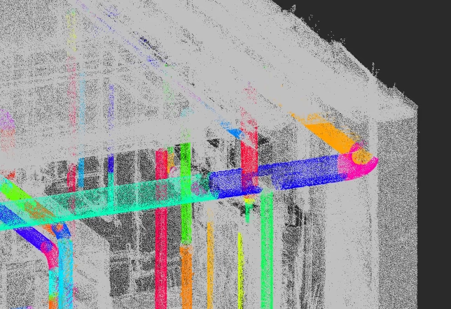
These display commands apply to point clouds in which nanoCAD has already detected features such as pipes, pipe fittings, planes and planar elements.
Reading pipe dimensions
Determine Radius (_NPC_RADIUS) and Determine Diameter (_NPC_DIAMETER) report the radius or diameter of detected pipes and cylinders at the command line.
Import of point clouds
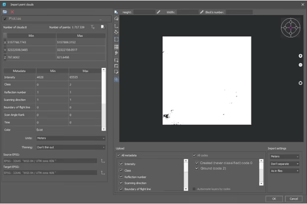
NPC_IMPORT has a redesigned import dialog with additional point cloud options.
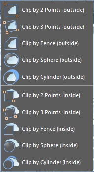
Separate commands for clipping inside or outside a boundary
Choose the command for the part of the point cloud you want to keep. You no longer need to switch between inside and outside clipping after starting the command.
Snapping to pipe bends
When tracing a pipe, you can now snap to its bend point.
3D solid modeling in nanoCAD Pro 23
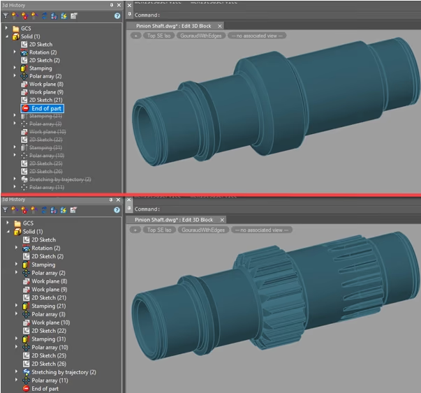
3D history
The 3D History tree now records sheet-metal flanges created in Mechanica. You can also reorder features when doing so preserves their dependencies.
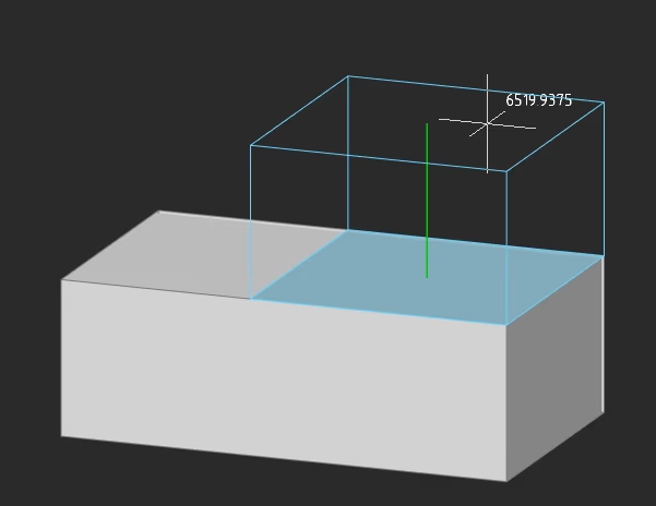
Presspull
PRESSPULL now lets you move part of a selected face.
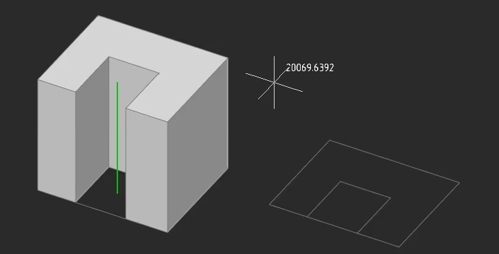
Extrusion
EXTRUDE now recognizes inner closed contours as holes.
Face alignment
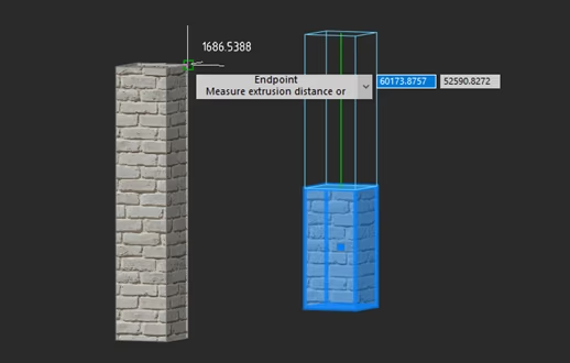
PRESSPULL and EXTRUDE now let you align the extruded face with an existing face in the model.
Section stretch
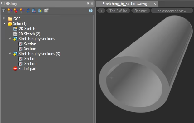
In parametric modeling, you can now use section stretching to create models with holes.
Parameter Manager
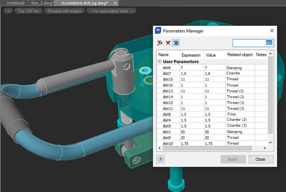
Use the search field in Parameter Manager to find a parameter.
Other changes
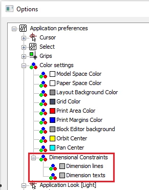
Set separate colors for dimensional constraint lines and text to make them easier to read against the grid. Use DYNCONSTRAINTSCOLOR and DYNCONSTRAINTSTXTCOLOR, or choose Color → Dimensional Constraints in Options.
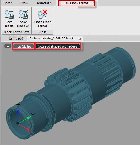
The view switches automatically to Top SW Isometric in these cases:
- When entering the sketch editing mode (PSADD), if there are no 3D constructions in the document and the view is oriented along one of the WCS axes;
- When entering 3D block editing mode (3DBEDIT).
In 3D block editing (3DBEDIT), the display also switches to Gouraud shading with edges.
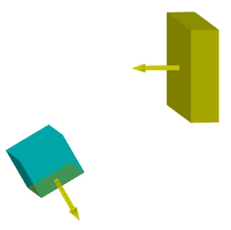
When applying a large 3D angular constraint (3DANGLE), you can now specify its rotation axis so the angular direction is unambiguous.

Fixes
Fixed a crash when extruding a contour that contains an ellipse or spline.
PRESSPULL now moves multiple selected faces correctly.
Fixed an angular constraint that could unexpectedly reverse its measurement direction.
Fixed an issue that prevented a 2D constraint from aligning a polyline vertex with a point.
Saving a 3D model now preserves the visibility of objects hidden through isolation.
Convert to Solid (CONVTOSOLID) now converts meshes located far from the origin.
What’s new in nanoCAD Mechanica 23
Assemblies
New assembly tools in Mechanica help generate drawings and parts lists from 3D models.
The file type can be changed according to the purpose:
- not specified
- part
- assembly
Assembly properties
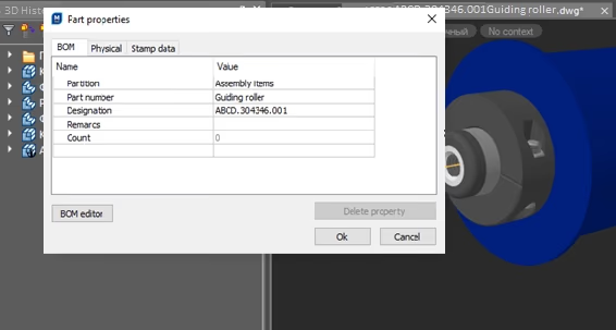
Each file type has its own properties for generating parts lists.
An unspecified file remains a regular DWG in which you can create 2D drawings and parts lists.
Part and Assembly files now have the following properties for generating a parts list from a 3D model:
- section
- name
- designation
- note
Part and assembly files now include title block, inventory and drawing-reference fields. When you generate a drawing or parts list, its title block can use those values.
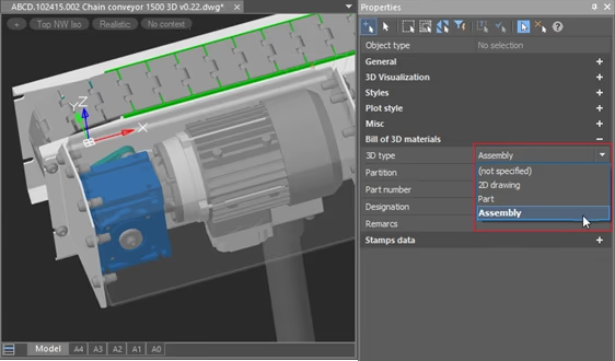
Document Properties Window
Assemble part files using external references. The resulting assembly file can itself be referenced by a larger assembly.
External references let you prepare drawings in the paper space of each part or assembly file without crowding the model space of the main assembly.
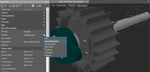
Properties window of an element set
When you copy a part or assembly block between files, it retains its properties.
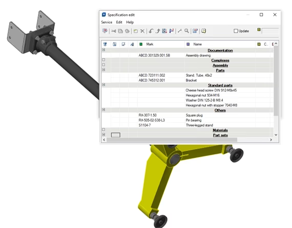
A parts list generated from the 3D model reads part and assembly names, designations, parts list sections and notes from the assembly.
Creating a parts list from a 3D model
Part and assembly blocks retain their properties when copied between files.
The parts list reads component names and designations, the section each component belongs in, and any notes stored with the assembly.
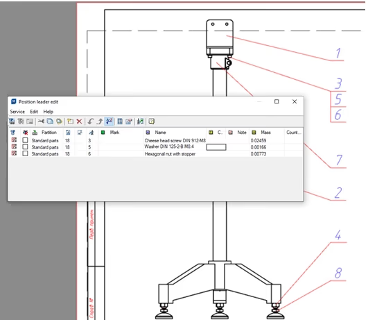
Place numbered callouts on assembly views. Item numbers stay in sync with the parts list editor.
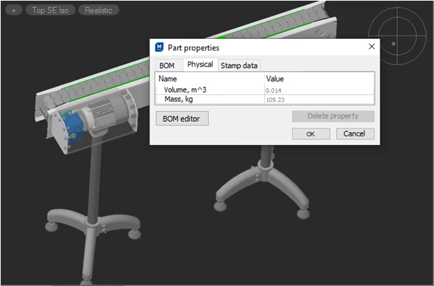
Calculating model weight
Assign a library material with a known density or define a custom material and enter its density. Mechanica uses it to calculate the weight of the 3D part.
Printing
You can now select several closed contours at once when defining drawing areas to print.
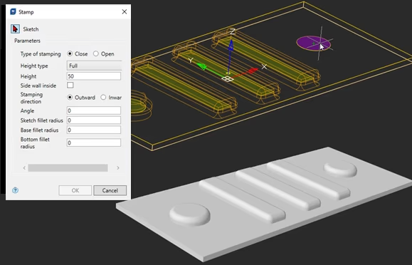
Sheet-metal flanging
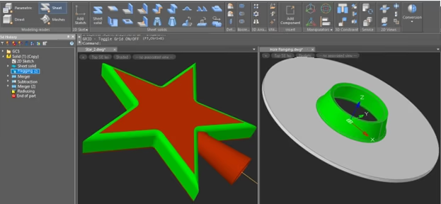
The new sheet-metal tool creates a flange along a planar edge of any shape or a chain of tangent edges.
What’s new in nanoCAD Construction 23
BCF (BIM Collaboration Format)
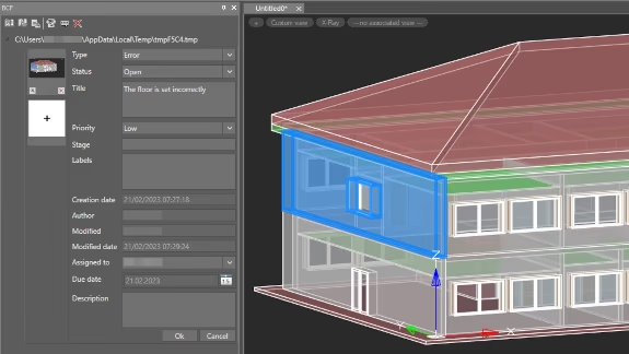
Use BCF to add and store review comments in a DWG file so project participants can discuss the model.
Material density
The Materials Library now includes a density field.
Fixes
Fixed a freeze when importing an object into the database.
IFC import now preserves door swing direction and the correct number of objects in groups.
Fixed errors when using the magnet tool to trace the boundary of a space.
Corrected the display of the Room dialog.
Double-clicking a DWG associated with Construction or Mechanica now opens that drawing with the correct module loaded.
What’s new in nanoCAD Raster 23
Raster 23 focuses on stability and performance. This release includes bug fixes and minor refinements to existing tools.
What’s new in nanoCAD Topoplan 23
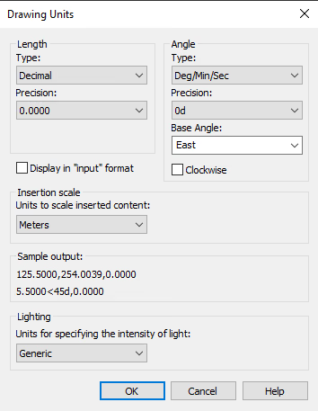
NEW_PLAN command
The New Topoplan command (NEW_PLAN) creates a new document with a nanoCAD_EarthWork_metric.dwt template preconfigured for the Topoplan module. The template is stored in the Templates folder. The following drawing units are set:
Alignment of coordinates
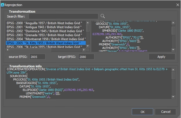
Coordinate Reprojection (NG_REPROJECTION) transforms survey object coordinates using EPSG codes.
Mesh simplification
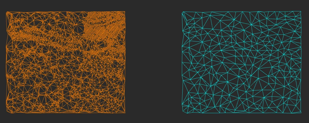
Simplify Mesh (NG_SIMPLIFY) reduces the number of triangles in a surface.
3D slopes
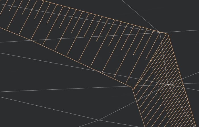
The 3D Slope command (NG_3D_SLOPE) creates a 3D slope on a surface or objects.
3D Polyline Offset
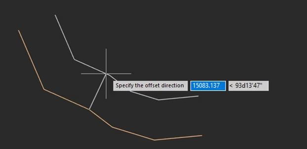
Use 3DPOLYOFFSET to create a 3D polyline at a specified offset from the original, much as OFFSET works on 2D geometry.
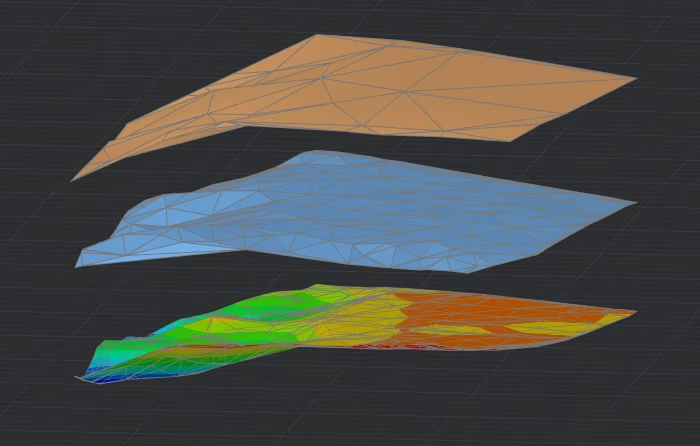
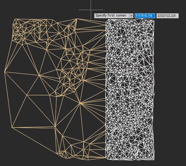
Difference between surfaces
The Height Difference command (NG_HEIGHT_DIFFERENCE) creates a new surface as a result of subtracting one surface from another.
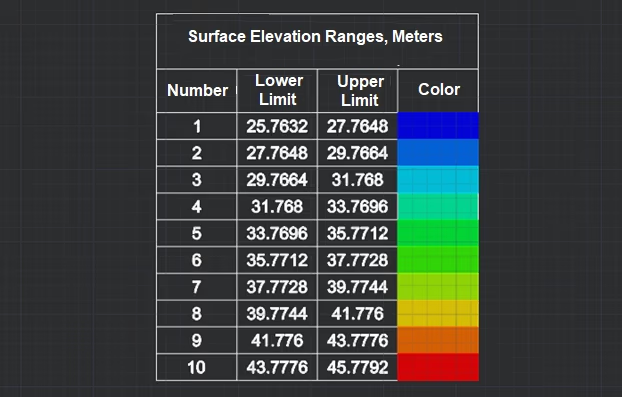
Elevation legend
NG_PAINT_ELEVATION_LEGEND adds a table to the drawing that explains the elevation colors on the selected mesh.
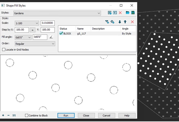
Topographic hatch patterns
The Fillshapes command (FILLSHAPES) fills the outline with conventional symbols on a rectangular, damer or arbitrary grid.
Creating geopoints manually
Run NG_CREATE_POINTS, pick a location in the drawing, then enter the point description and elevation.
Creating a geopoint group manually
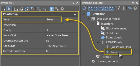
New command Create a Geopoint Group Manually (C3D_CREATE_COGO_POINT_GROUP). The command options are set in the Properties bar.
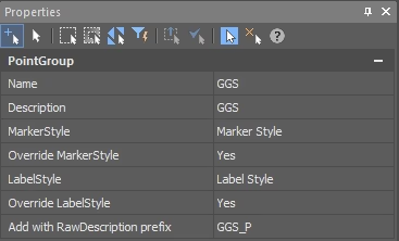
Creating groups from point descriptions
Command (C3D_CREATE_COGO_POINTS_GROUPS_BY_RDESCR) - automatic creation of dot groups. The command has no options. All points have the same raw description and are combined into a group.
Edit, rename or delete a group
Double-clicking on the name of a group of geopoints in the Drawing Explorer, the renamed group is now not started, but editing its parameters in the Properties bar.
It is now possible to delete groups. It is done from the Drawing Explorer by using the Remove From Context Menu command of an unnecessary group of geopoints. A named group of geopoints can be renamed by selecting the Rename command from the context menu of the named group.
New geopoint grips
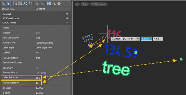
Geopoints now have separate grips for rotating the label and the marker about the insertion point. You can also enter their rotation values in Properties:
Creating geopoints from points and text
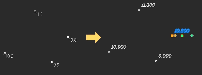
The Create point by point and text command (NG_CREATE_POINTS_BY_TXT) creates geopoints using points (circles, blocks) and text objects (texts, multiline texts) that are at a specified distance from them.
Geopoint Export
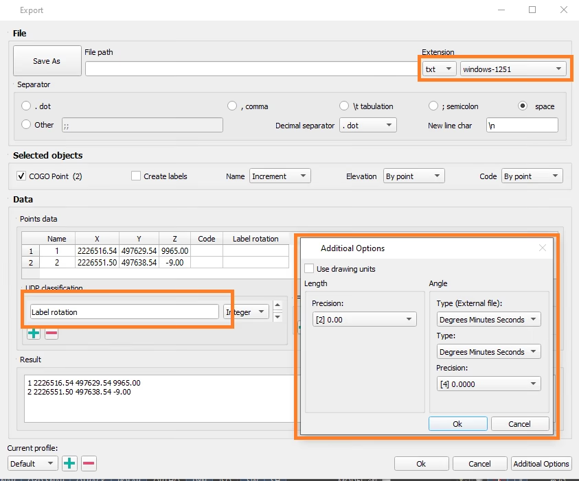
The Export Geopoints command (NG_EXPORT_POINTS) allows:
- export geopoints, blocks or plain points as TXT, CSV or SDR files and optionally create drawing labels;
- save the rotation value of the label or other user attributes when exporting to an external file;
- select encoding.
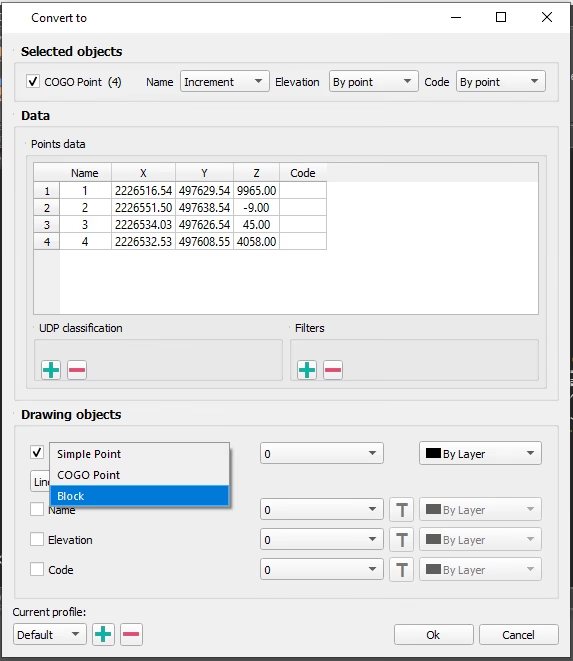
Point Conversion
Use NG_CONVERT_POINTS to switch between plain points, geopoints and blocks.
Creation and editing of geopoint tag styles and markers
Use the context menu in Drawing Manager to create custom geopoint marker styles (C3D_CREATE_COGO_MARKER_STYLE) and label styles (C3D_CREATE_COGO_LABEL_STYLE). Adjust the new style in Properties.
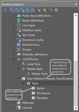
User-defined geopoint properties
Use custom properties for survey data that does not fit the standard geopoint fields.
- String: stores text, including letters and digits.
- Integer: stores whole numbers.
- Double: stores numbers with a fractional part.
- Boolean: stores a Yes/No (true/false) value.
The user-defined properties of the geopoints are grouped into user-defined property classifications. A classification can be created, filled in with user-defined or deleted properties.
Batch-loading georeferenced raster images
Batch-load georeferenced TIF and ECW rasters with NG_IMPORT_RASTERS. Use it to assemble a base layer from the tiles of a large orthophoto.
Search for key lines on surfaces
NG_KEY_LINES identifies terrain features such as valley lines and ridges on a surface.
Deleting mesh edges
Delete Edge (NG_MESH_EDGE_DELETE) can now remove several edges at once.
Coloring a mesh by elevation
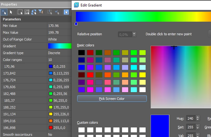
The revised Color Mesh by Elevation tool (NG_PAINT_ELEVATION) lets you:
- set the color gradient;
- Specify minimum and maximum values;
- Set a color outside the specified range;
- Select the type of gradient (continuous or discrete);
- save a gradient to a file or load one from a file.
Geopoint Import Panel (Improved)
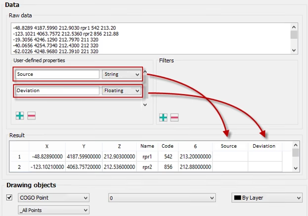
Define new point properties directly in Import Geopoints (NG_IMPORT_POINTS). Each property adds a column to the results table and is assigned to the imported points:
Data typing (improved)
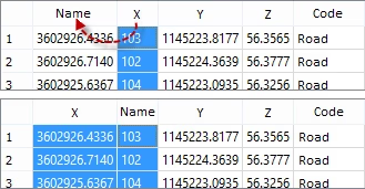
Column headers identify the data types mapped from a text file. To correct a mapping, drag one column header onto another. The mapping changes while the data stays in place.
Other improvements in geopoint import
Points imported as blocks now follow the drawing scale. Previously they always used the same scale.
Import Geopoints (NG_IMPORT_POINTS) now lists the existing geopoint groups and offers the available creation options when the dialog opens.
Block names generated when importing geopoints as blocks no longer include a date.
The geopoint import dialog now sorts existing block names so you can find a block more quickly when importing points from a text file.
Expanding a group box no longer reveals objects that should remain hidden.
The source-selection dialog now ignores differences between uppercase and lowercase letters.
Importing several files at once no longer creates duplicate entities for each file.
When several files are selected, changing the starting row now updates the individual file results as well as the combined list.
KML/KMZ import (improved)
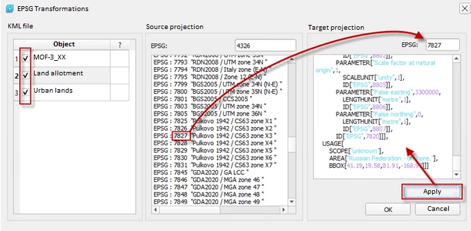
KMLIMPORT can now reproject KML or KMZ data between survey and geodetic coordinate systems using EPSG codes.
KML/KMZ file import (improved)
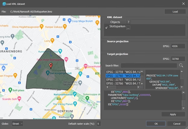
The updated import dialog shows the loaded files on a globe. Choose a map or satellite image for the background.
Search for a projection by number or name and inspect the selected projection’s parameters.
The view zooms to the imported objects.
Change of scale of conventional geopoints and signs
Changing the survey scale now prompts you to rescale geopoints and map-symbol blocks already in the drawing.
Create TIN by Points (improved)
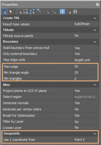
When building a TIN from geopoints with NG_CREATE_TIN, you can read elevations (Z coordinates) from a custom attribute and filter by the angle between triangle edges.
Changing the insertion point for layout frames
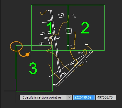
Create View Frames now lets you change the insertion point for layout view frames.
Changing the anchor point of the frame is convenient in case of designing routes, as they can go in any direction. This is also true for tablets, where normally the numbering goes from left to right and from top to bottom. But when you try to insert the second row, it is already inconvenient to use the anchor point from bottom to left.
Layout frames now follow the viewport boundary
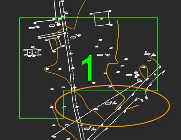
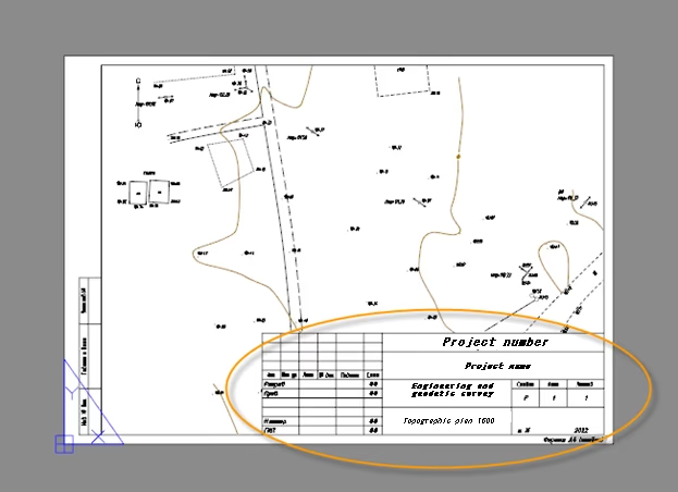
Earlier releases created rectangular layout frames without accounting for the title block. A frame now follows the actual viewport boundary.
This makes a difference on an A4 landscape sheet, where the title block occupies a large area and can cover part of the model.
Other changes and improvements
After a LandXML import (NPC_IMPORT_LANDXML), the view now pans to the imported data.
Properties now shows the correct values for two parameters of Volume Between Models (NG_VOLUMES).
Custom properties must now have a name.
Locking a geopoint now prevents moving, copying or stretching it. Label visibility can show or hide the label independently of the selected style.
Moving a geopoint label no longer produces unwanted masks.
You can now rotate a geopoint label after moving it.
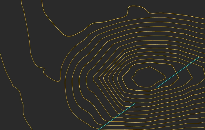
Support for soft contours on Civil 3D surfaces:
The toolbar now refreshes automatically after you create a geopoint label style (C3D_CREATE_COGO_LABEL_STYLE) or marker style (C3D_CREATE_COGO_MARKER_STYLE).