nanoCAD 25 introduces new ways to edit drawings, exchange files and work with 3D models. The release notes below cover both the platform and its specialist modules.
What’s new in nanoCAD 25
New platform features
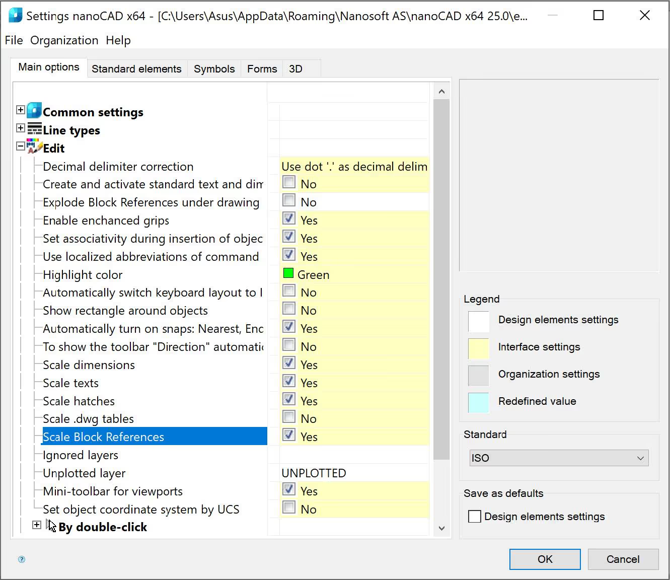
Use the new Scale Block Reference setting in PARAMS → Main Options → Edit to turn block scaling on or off. By default, a block scales when its symbol scale changes.
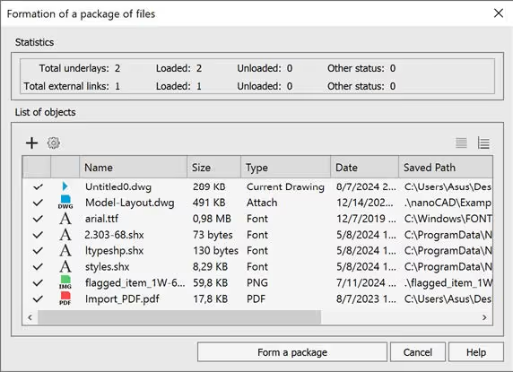
The Create Transmittal (ETRANSMIT) dialog has new file-type icons and now lets you select multiple files using SHIFT and CTRL.
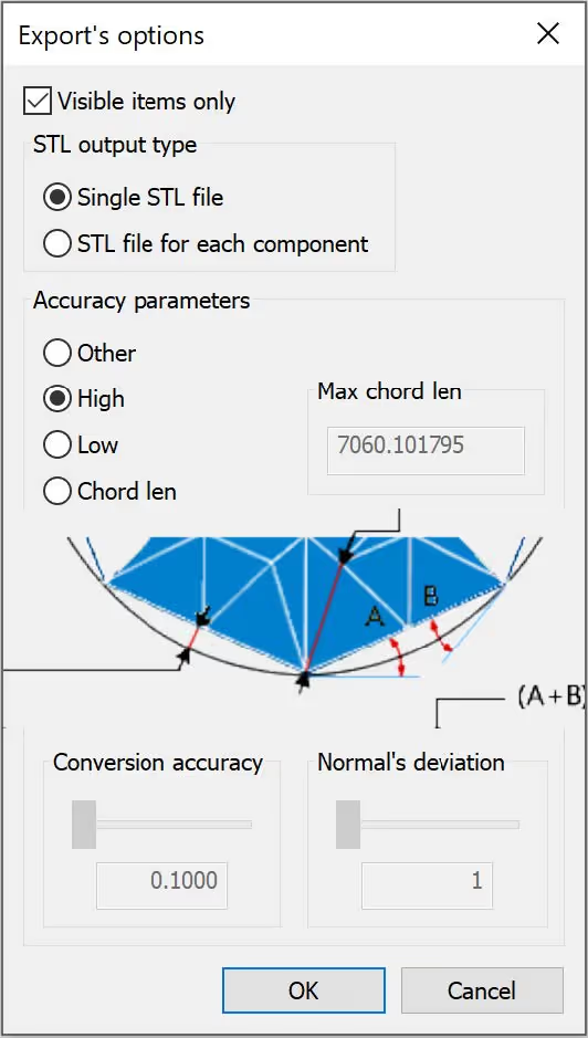
Use EXPORT to set the accuracy for STL (*.stl) format by specifying the maximum distance between adjacent points (Maximum chord length).
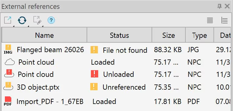
New icons make unused files easier to identify in External references (EXTERNALREFERENCES).
Use the new Dimensional Constraint (DCAUTO) command to add parametric dimensions in sketch editing mode, much as you would with MDIM.
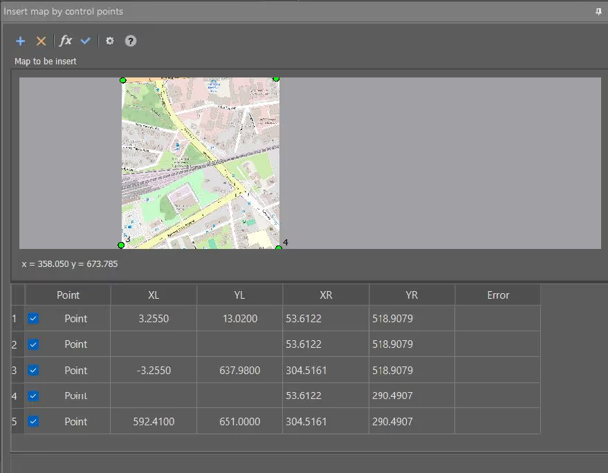
The new Insert Map by Control Points toolbar lets you position a raster map underlay using control points. Open the Map Underlay (MAPVIEW) dialog, go to Raster Maps, select the options you need, check By control points at the bottom of the dialog and click on the OK button.
Export
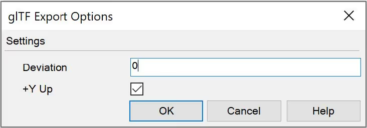
The formats GLB and GLTF are now available in EXPORT. Both formats store complete 3D scenes in compact files that load and process quickly.
You can also specify how to orient the Y axis (up) when exporting GLB or glTF files.
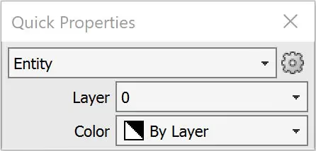
Quick Properties toolbar
A floating Quick Properties (QUICKPROPERTIES) toolbar gives you access to commonly used properties.
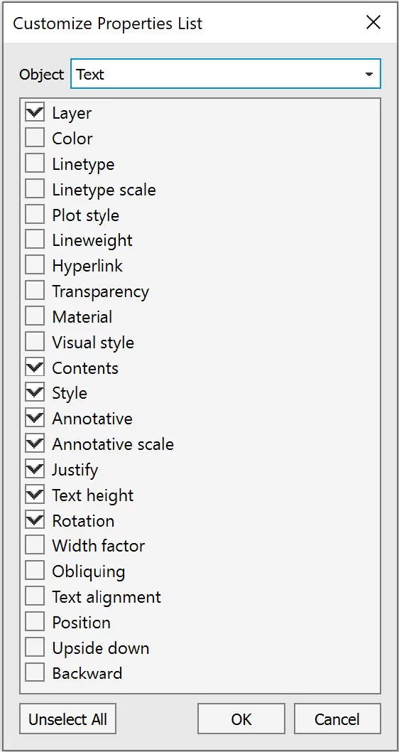
Click Settings to open the Customize List of Properties dialog and choose which properties the floating toolbar shows for each object type.
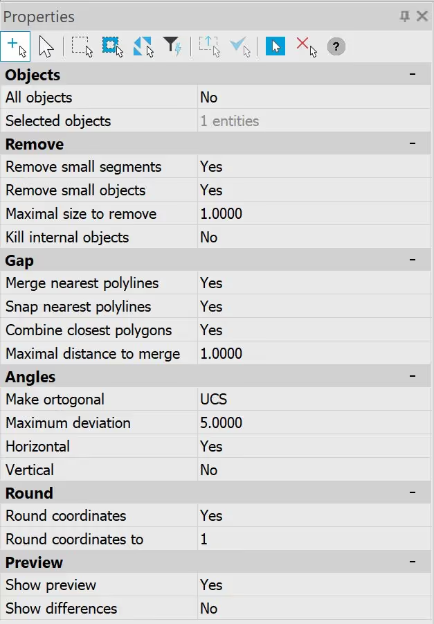
Automatic Vector Correction
Use Vector Correction (AUTOVC) to correct drafting errors and deviations introduced by automatic or semi-automatic tracing. The command supports these object types:
- line;
- polyline;
- arc;
- circle.
Use automatic correction to:
- remove objects smaller than the specified size;
- reconnect objects;
- join fragments into a single object;
- align lines along standard addresses (UCS, Orto-grid), if their deviations do not exceed the value specified by the user;
- change the rounding order of the coordinates of the objects in the drawing.
Collecting diagnostic information after a crash
After a critical error, nanoCAD can now collect diagnostic information automatically with ReportProblem.
The tool creates a time-stamped folder and packages the files as a ZIP archive. Save a local copy with Save Reportor create an email in EML format with Send Report).
Batch File Processing
In Batch File Processing (BATCHPROCESS) , the default processing profile now includes Remove Proxy Objects (RMPROXY). This step is off by default. When enabled, it can remove proxy objects with graphics, without graphics, or both.
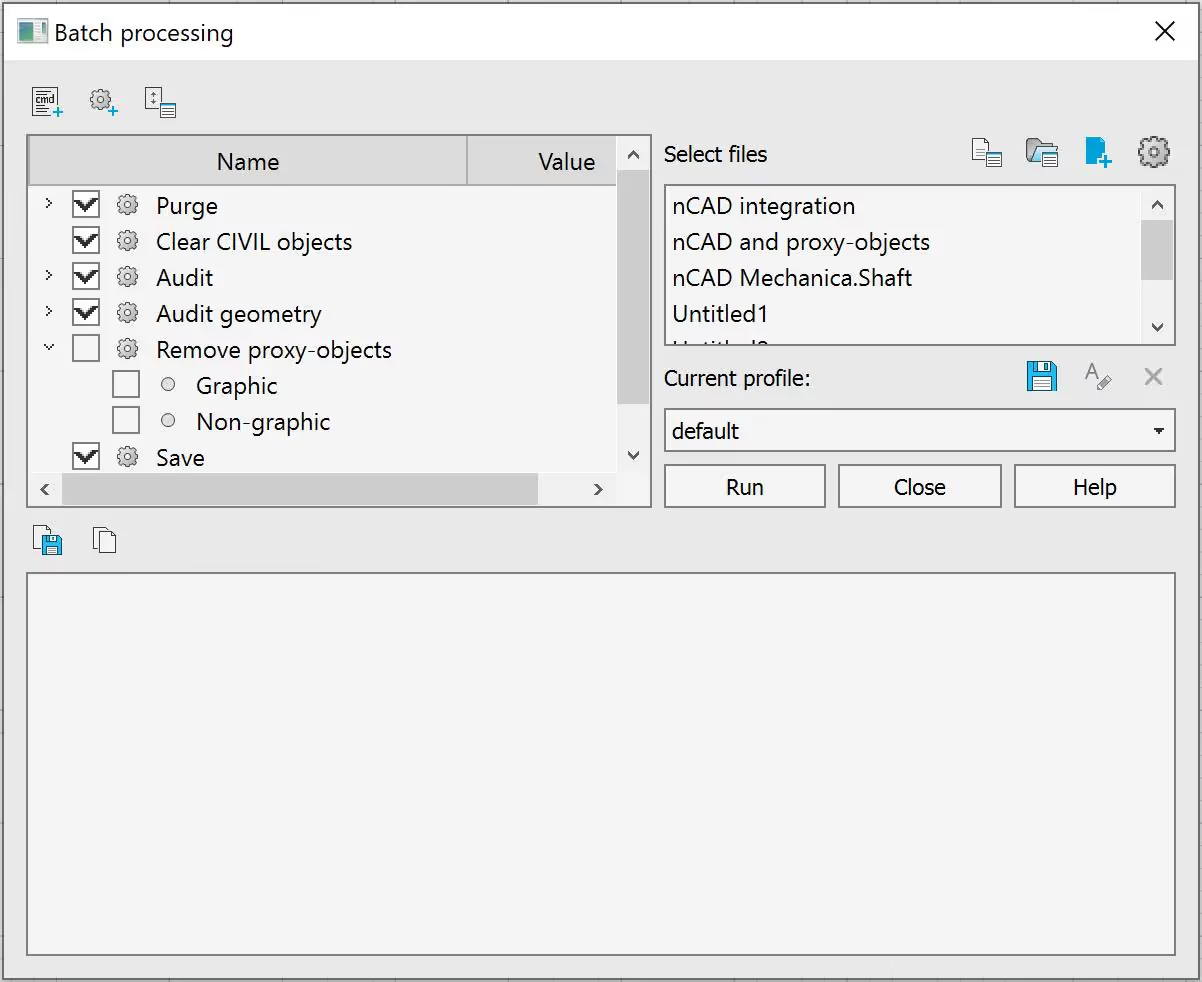
Use Add the current file automatically to include the open drawing in the batch.
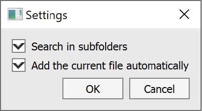
By default, the setting is enabled and when you execute the command Batch File Processing (BATCHPROCESS) the current drawing is added to the list of Selected Files automatically.
The Selected Files list now accepts both DWG (drawing format) and DWT (drawing template format).
Sheet sets
A new dialog lets you configure the Sheet List Table. Set the table style, title and columns, then choose a saved sheet set or select the sheets you want to list.
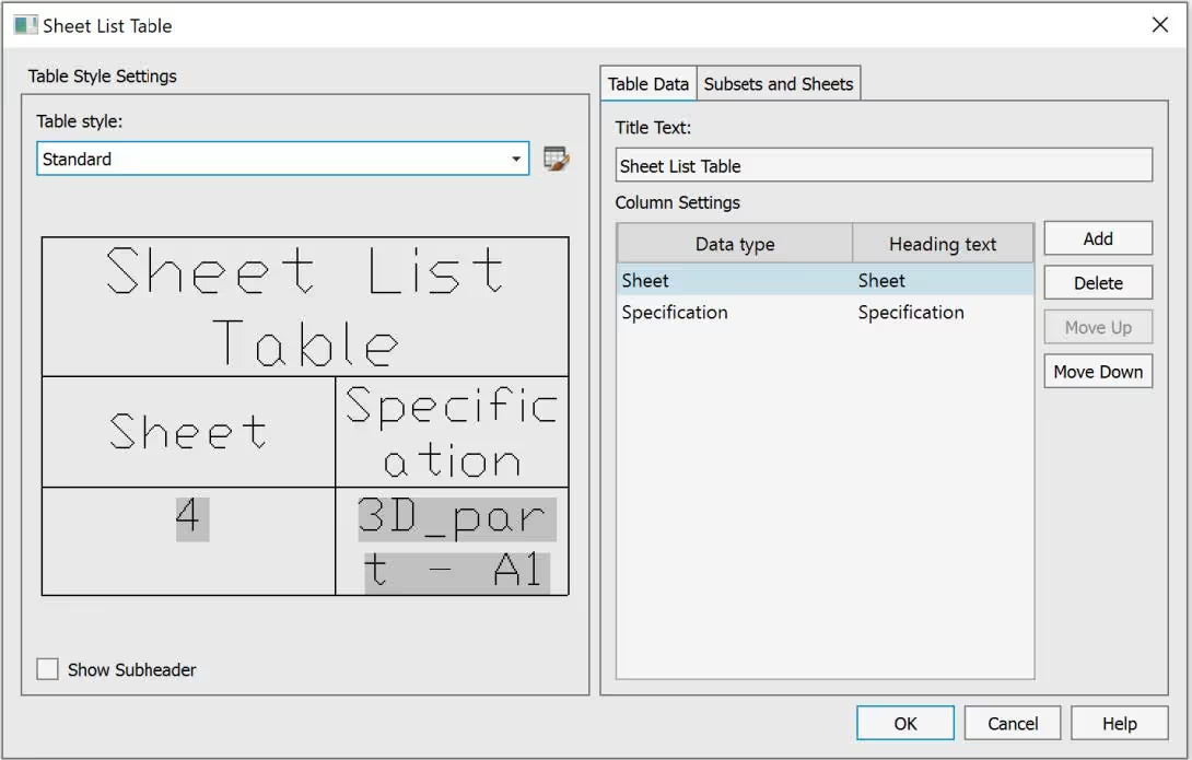
nanoCAD now associates sheet set files with the DST extension. Opening one loads the associated drawings and launches Sheet Set Manager (SHEETSET) at the same time.
Drag sheets to move them within a set or group in Sheet Set Manager (SHEETSET).
When you choose Rename and Renumber Sheet in Sheet Set Manager (SHEETSET), the Number field is selected automatically.
On the Sheet List tab in Sheet Set Manager, use the new publish menu for selected sheets or the entire set. Choose from the following options:
- publish to PDF;
- publish to a plotter;
- publish to DWF;
- publish to DWFx.
You can also publish individual sheets, groups or a whole set from the context menu in the sheet set tree.
The suggested filename for a multi-sheet plot now matches the sheet set name. Previously it used the name of the first sheet.
Plotting
Select Create Bookmarks in Print as PDF or Internal PDF Plotter to create PDF bookmarks for sheets and views.
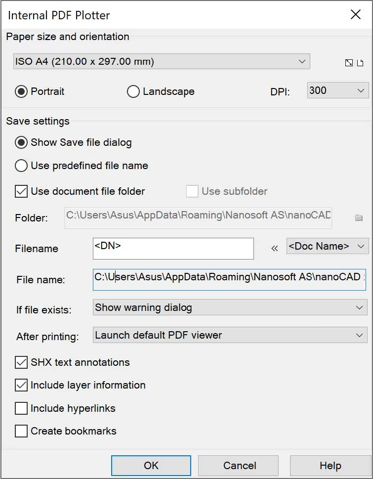
Select Include hyperlinks in the internal DWFx, DWF or PDF plotter settings, or in Print as PDF, to keep hyperlinks active in the exported document.
All internal plotters can now save device settings in PC3 files for reuse on other computers.
Select Use subfolder in any internal plotter to save output in a folder named for its format (DWFx, DWF, EMF, PDF or Raster). The option is available when Use default filename and Use Document File Folder are enabled.
You can now put the PC3 plotter configuration beside the DWG file or in the standard plot configuration folder, C:\Users\User_name\AppData\Roaming\Nanosoft AS\nanoCAD x64 25\PlotConfigs.
Checking network plotters is faster. The search now takes only a few seconds to time out on a disconnected or unavailable plotter.
Run PARAMETERSCURLAYOUT to open the Page Setup dialog for the selected sheet.
Tables
Run Recalculate all tables in the drawing (RECALCTABLES) to refresh every table in the drawing. The command bypasses automatic recalculation and report locks and applies both Update reports and Recalculate.
You can now load a nanoCAD table (TABLE) directly from XLSX files without installing an office suite.
In the nanoCAD table editor (TABLE), the full editor now includes formatting buttons for Underline, Strikethrough and Overline. You can apply them to multiple cells at once.
Text
Use the new system variable MTEXTFIXED to control how hard-to-read text appears while you edit it. This includes very small, very large and rotated text:
- MTEXTFIXED = 0 (or 1) – the text is displayed according to the size and rotation in the drawing;
- MTEXTFIXED = 2 (default value) – the text is displayed in a convenient size and horizontal direction.
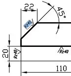
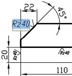
Use the following shortcuts for superscript and subscript in Multiline Text (MTEXT):
- superscript – Ctrl + Up Arrow;
- subscript – Ctrl + Down Arrow.
These shortcuts also work in nanoCAD tables (TABLE).
Use these shortcuts to format single-line text (TEXT):
- strikethrough — %%K or CTRL + K;
- underlined text – %%U or CTRL + U;
- overline — %%O or CTRL + O.
For all tools to create and edit Multiline Text (MTEXT) and single-line text (TEXT), the same paragraph alignments are now available in the same order: Align left, Align center, Align right, Justified, Distributed.
The Paragraph dialog on the Text Format (MTEXT) toolbar now offers additional controls.
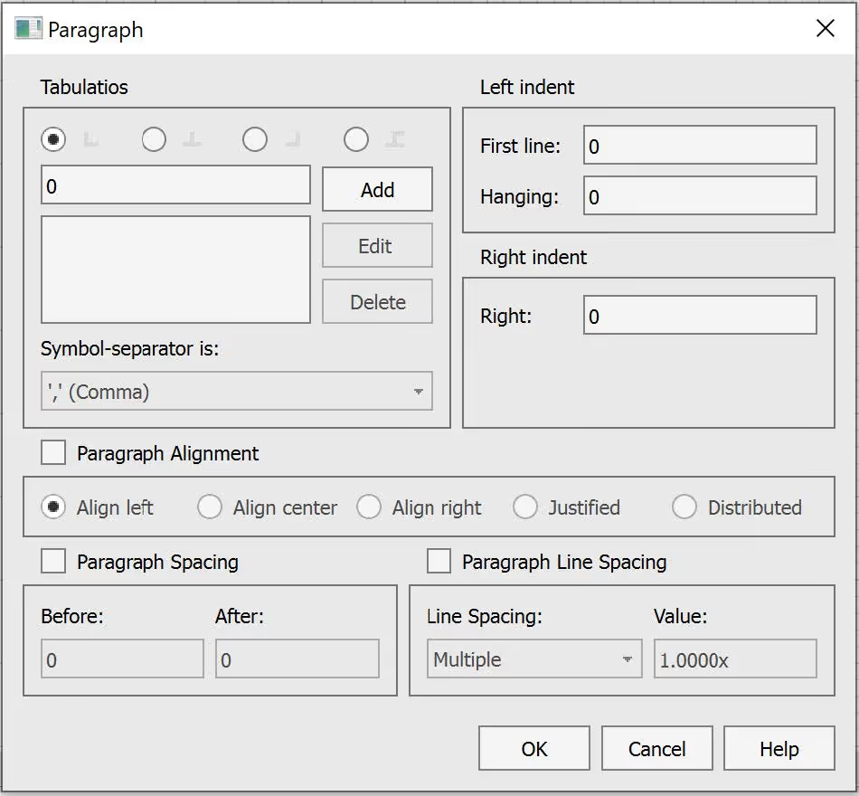
New settings include:
- tab alignment, number of stops and stop positions,
- options and indentation values,
- paragraph alignment.
You can now adjust spacing before and after a paragraph and line spacing within it.
nanoCAD now warns if the overlap factor is outside the valid range in Background Mask (BACKGROUNDMASK).
Templates
Create a drawing from a template ( DWT ) directly from the nanoCAD menu.
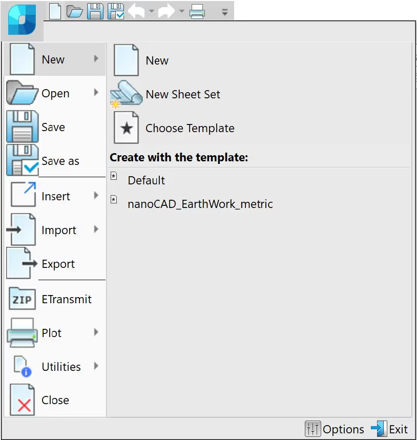
The menu shows a limited set of templates. For a template that isn’t listed, open Choose Template or edit the List of Template Names under Use of Templates in Options (OPTIONS).
The command Choose Template (TEMPLATESDIA) lists the available drawing templates.
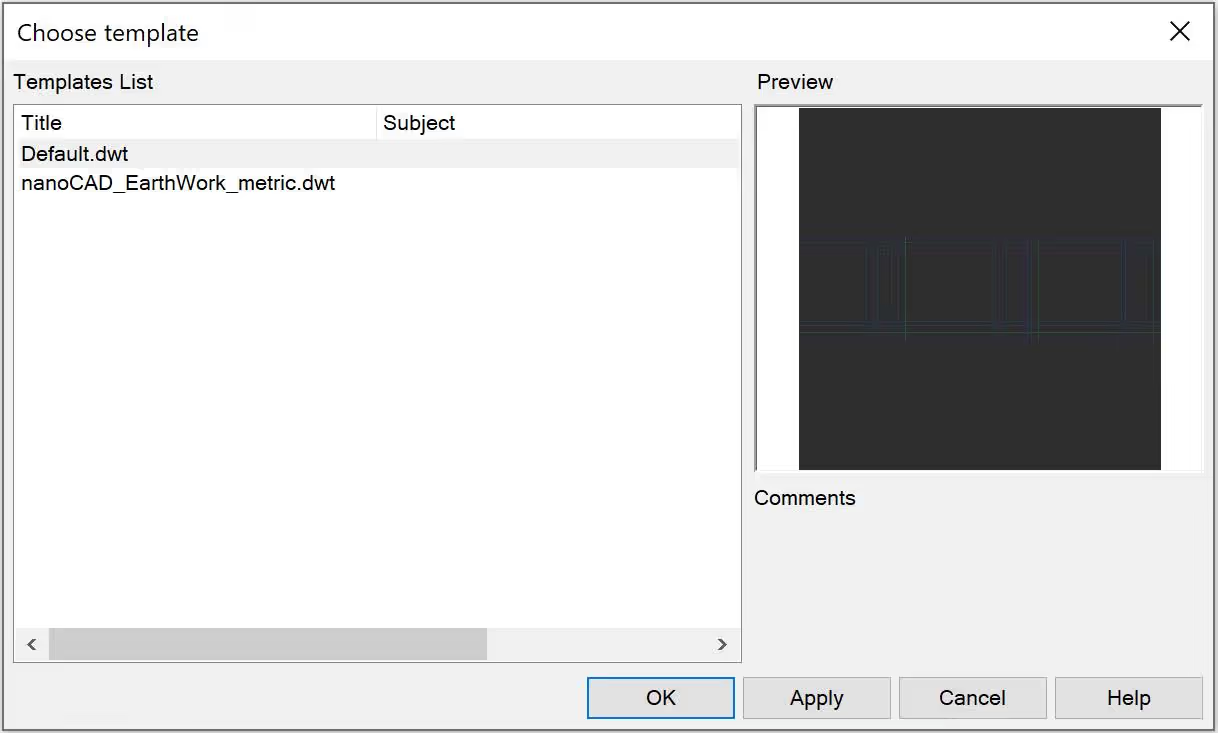
You can add or delete a template by selecting the appropriate command from the context menu. The order of the templates can be changed by simply dragging and dropping.
Toolbars
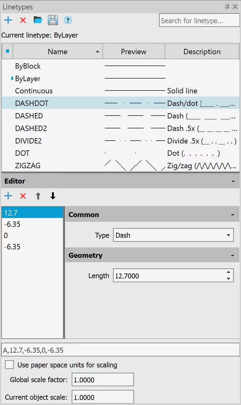
The controls from the classic Linetype Manager (STYLEEDITCMDCLASSIC) dialog now appear in the Linetypes (STYLEEDITCMD) toolbar. Edit the selected linetype or create a new one there.
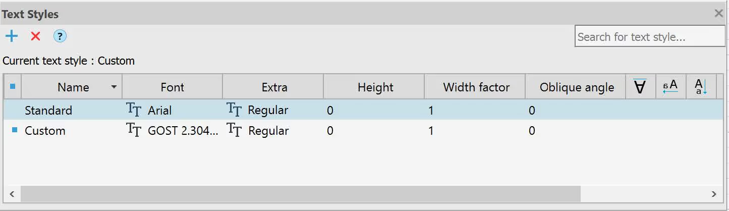
The controls from the classic Text Style (TEXTPROPSCMDCLASSIC) dialog now appear in the Text Styles (TEXTPROPSCMD).
Groups
If you select exactly the same objects as an existing group when running GROUP and -GROUP, a command-line prompt asks whether you want to create the duplicate group.
The GROUP context menu now disables Ungroup, Add to Group and Remove from Group when the selection mixes existing groups and individual objects.
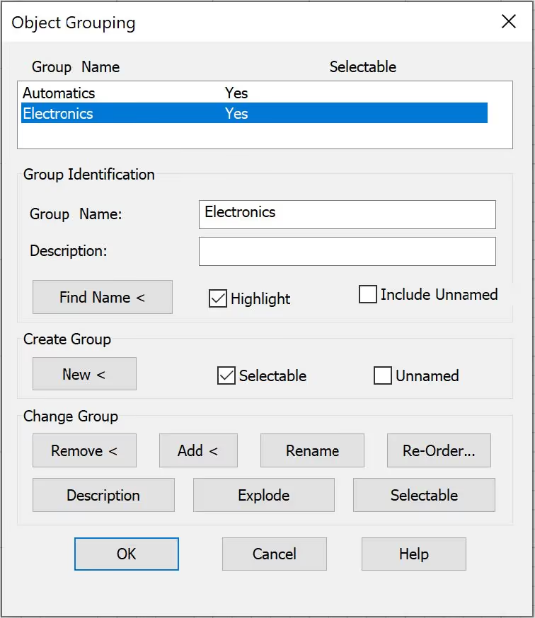
In the Object Grouping (GROUPCMD), the mechanism to highlight objects in the selected group on the screen has been changed. Now the Object Grouping dialog does not close. When the option Highlight is enabled, the group whose line is selected in the dialog list is highlighted on the screen.
Updated dialogs
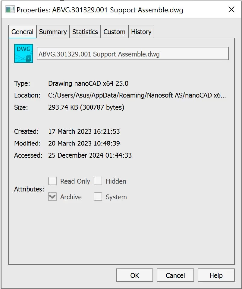
Updated dialog: Drawing Properties (DWGPROPS). You can resize the dialog, and nanoCAD remembers the widths of custom-property columns. The layout has also been updated.
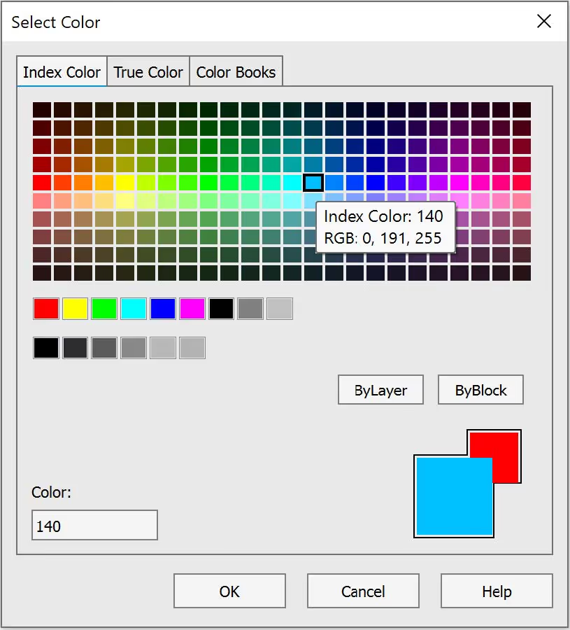
Updated dialog: Select Color (COLOR). The dialog now remembers its position. Use the eyedropper to sample any color on screen, or specify a color in HSV mode. You can also change the color number on the True Color using the keyboard arrows.
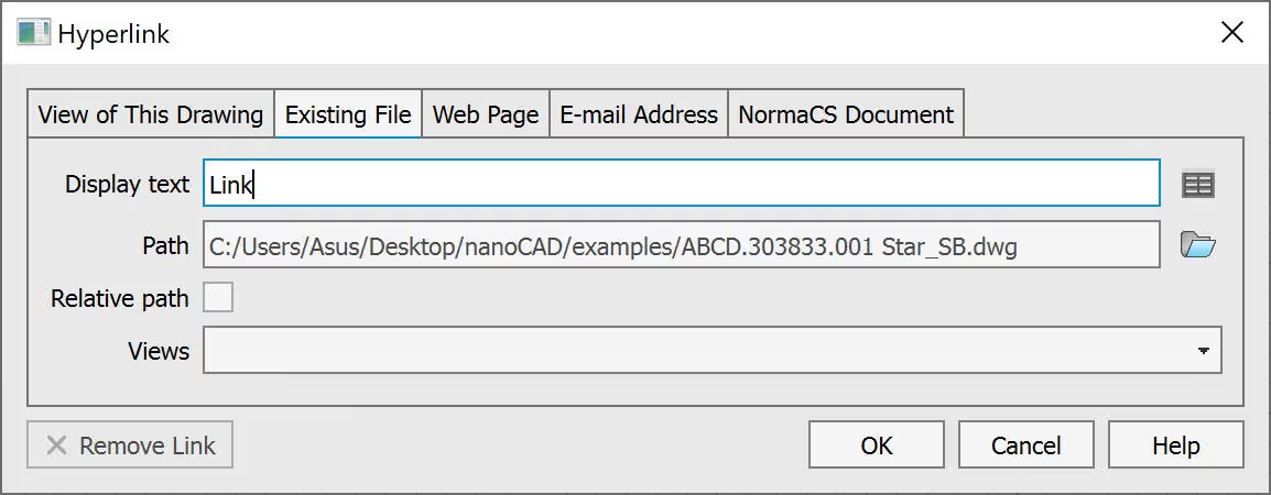
Updated dialog: Hyperlink (HYPERLINK).
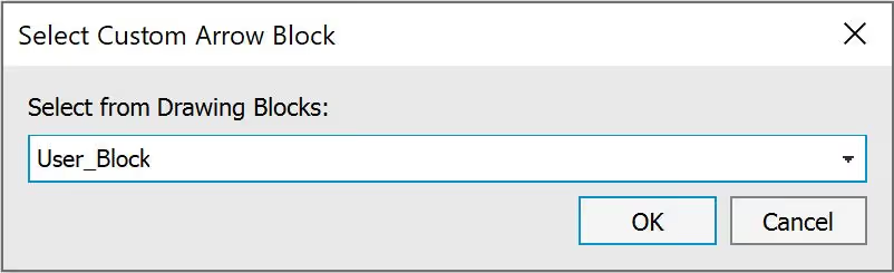
Updated dialog: Select Custom Arrow Block.
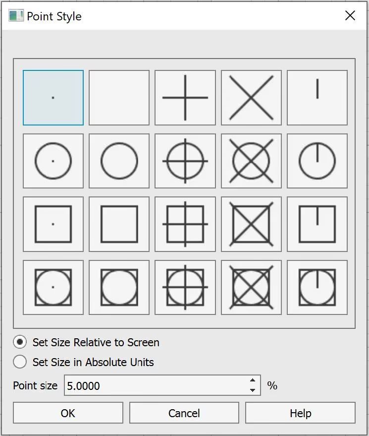
Updated dialog: Point Style.
Other improvements
Run Replace Block with Other Block (BLOCKREPLACE) to replace the selected blocks with one specified block. Select the blocks first or respond to the command-line prompt.
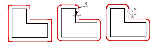
Use the new system variable OFFSETGAPTYPE, which controls the shape of outside corners when offsetting a polyline (OFFSET):
- OFFSETGAPTYPE = 0 (default value) – the offset lines extend to form a corner;
- OFFSETGAPTYPE = 1 — fillets the corner with a radius equal to the offset distance;
- OFFSETGAPTYPE = 2 — chamfers the corner. The perpendicular distance from the original corner to the chamfer equals the offset distance.
The Intersection object snap now works at spline self-intersections (SPLINE).
In the toolbar External references (EXTERNALREFERENCES) now uses distinct icons for these external reference states: Not Found, Unloaded and Unreferenced.
You can now change the background Transparency (TRANSPARENCY) of raster images in TIF (TIFF).
Added the new command Send by Email (ETRANSMITDWG) the nanoCAD button. The command generates an EML file to send the current drawing by email.
Buttons now have tooltips in Create Transmittal (ETRANSMIT), and for layer parameter icons in the toolbar Layers (LAYERSQUICK).
You can now expand or collapse all property groups at once in Properties (INSPECTOR). To expand or collapse all groups, click + or − next to any group name while holding SHIFT.
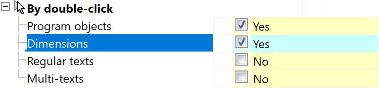
Double-click behavior has changed. If Dimensions is turned off under nanoCAD Configuration (PARAMS)→ Main Options → Edit → Double-click, double-clicking opens the multiline text editor (MTEDIT).
Revised the warning shown when a drawing contains many external references (XREF).
Updated the descriptions under System configuration in Options (OPTIONS) to explain when changes take effect.
You can now find Save Layout As… (LAYOUTTOTEMPLATE) on the Model and Layout tab context menus.
You can no longer change the Multiple Lines setting when editing a multiline attribute in Block Attributes Manager (BATTMAN).
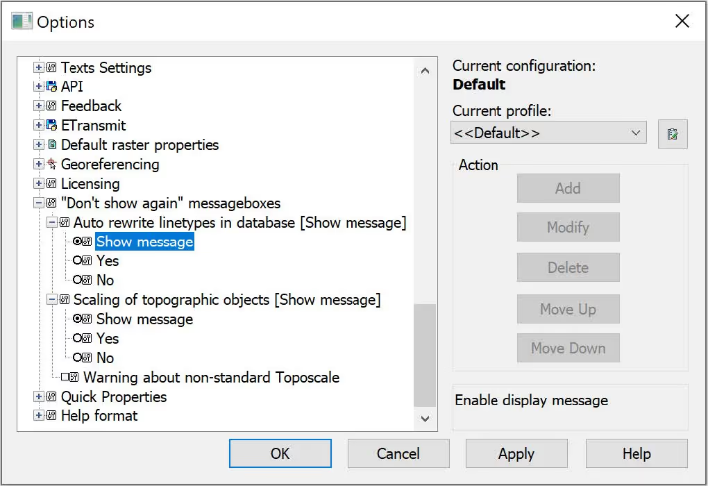
The new “Do not show again” section in Options (OPTIONS) lets you manage warnings you have chosen to hide.
Information, warning and error messages are now easier to distinguish.
You can assign a color or finish (COVERINGBROWSER) to an entire solid or to an individual face. A warning now appears if you select a vertex or edge.
Mechanica Module
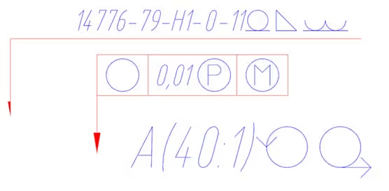
Symbols that retain their proportions
Weld symbols, geometric tolerance symbols and view rotation or reversal symbols now retain their shape when the surrounding text is slanted or condensed.
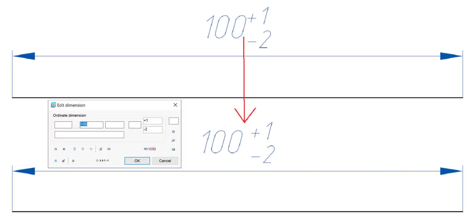
Spacing between a dimension value and its tolerance
A space can now separate a dimension value from its tolerance to improve the appearance of slanted fractions in DWG text. The space appears when:
- the dimension tolerance is asymmetric;
- the upper tolerance is not zero;
- the tolerance display includes the nominal dimension and both deviations.
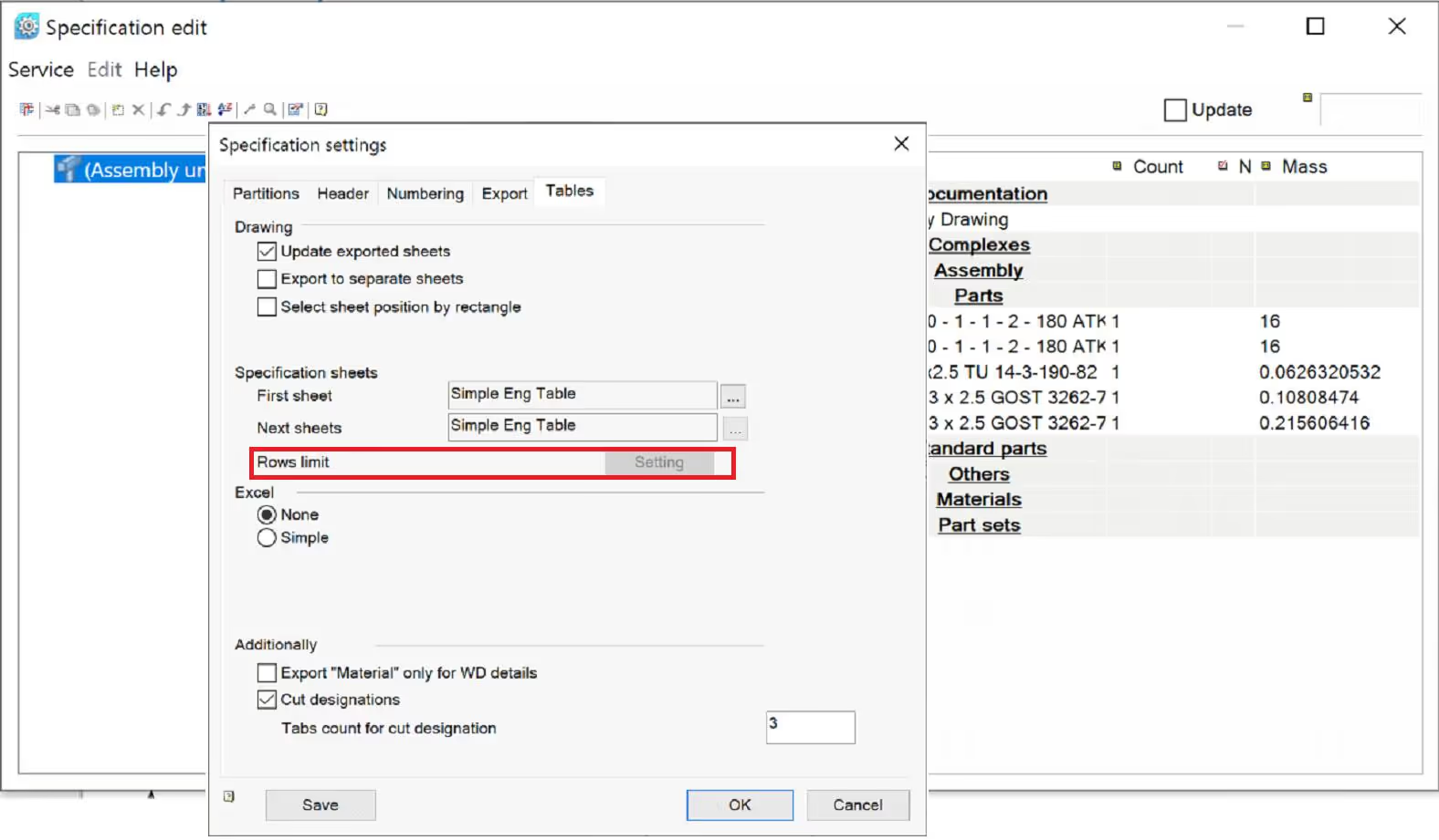
Multi-column parts lists
A parts list embedded in a drawing can now span several columns. Under parts list settings, open the Table tab and use Row Limit to set the maximum number of rows in each column.
Point Clouds
Changes to commands
Point cloud database commands have moved to the new Storage module in the Point Clouds application.
Project Manager
Fixed the following problems in Project Manager (NPC_PROJECT_MANAGER):
- freezes during import;
- a crash after renaming a block;
- shifted flight lines.
Improved RCS point cloud import.
Fixed a crash when closing nanoCAD after importing a point cloud.
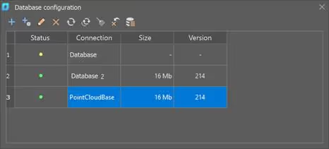
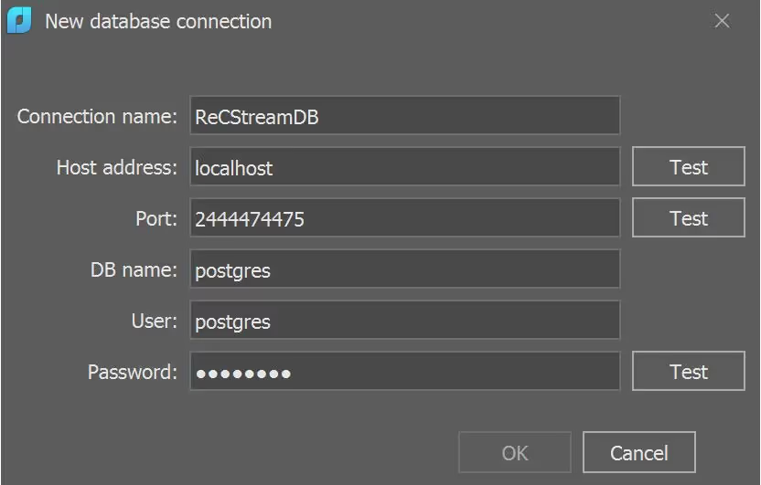
The database connection panel now validates parameters, records a connection log and supports a default connection mode.
Point acquisition time now uses GPS week time instead of GPS time.
Commands added DB_UNDO/DB_REDO for undoing and redoing semi-automatic edits to point clouds.
The new system variable POINTCLOUDSECTIONUCS controls how the UCS is set when you create point cloud sections.
Point cloud storage now maintains an index dictionary for every attribute. View the dictionaries in Point Cloud Information (NPC_INFO).
Revised level-of-detail generation makes point clouds easier to read.
The problem of importing PTS files with normals has been solved.
Undo and Redo now work correctly when creating regions in the point cloud import preview.
View Mode
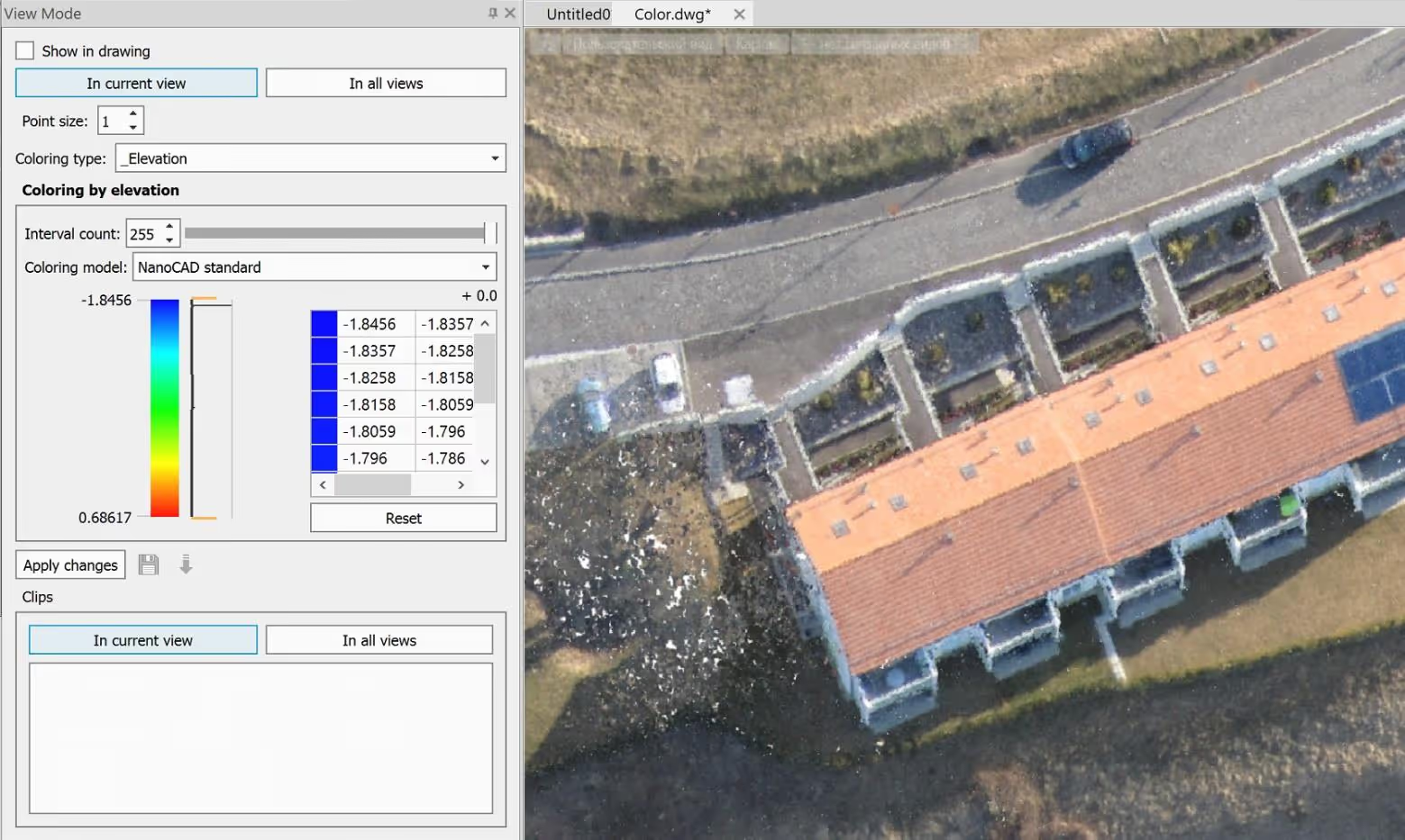
The View Mode (NPC_VIEWMODE) dialog has been replaced by a toolbar with additional controls.
New Coloring Options for Point Clouds
Independent color buffers let the preview use a different color scheme from the point cloud. Multiple threads can process color data in parallel.
New metadata type: spatial dimension
Point cloud metadata now supports spatial dimension (topological, correlation or fractal). It is available in database storage, histograms, coloring, the API and metadata structures.
Coloring Point Clouds by Dimension
Points can now be colored by spatial dimension. The new toolbar interpolates between colors in the selected scheme in View Mode using normalized values.
Linking Point Cloud Classes to Layers
Point cloud classes are no longer linked to drawing layers. Importing a cloud no longer creates layers for its classes or fills in the Note field, and the Layers dialog no longer controls class visibility. Manage classes in View Mode.
Topoplan Module
New Commands in the Topoplan Module
New commands to convert surfaces:
- NG_CONVERT_TO_SURFACETIN — converts meshes, polygon meshes and 3D faces into a civil TIN surface;
- NG_CONVERT_FROM_SURFACETIN — converts a civil TIN surface back into a mesh, polygon mesh or 3D faces.
The new command Add Drawing Objects (NG_MESH_ADD_OBJECTS) adds the following types of objects:
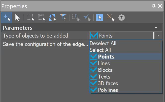
Choose whether to preserve existing triangle edges or rebuild them.
The new command Create Contour Lines from Objects (NG_MARK_AS_CONTOUR) lets you mark polylines and 3D polylines as contours so you can add labels and downhill ticks.
The new command Create Points by Resection (NG_CREATE_POINT_BY_RESECTION) creates a survey point by angular resection.
The new command Create a Coordinate System (NG_NEW_CRS) lets you define a coordinate system for later coordinate transformations.
The new command Information about Coordinate Systems (NG_CRS_INFO) lists the parameters of the coordinate systems in the Topoplan database.
Projecting Objects on a Surface
You can now project dynamic blocks onto a surface with NG_MESH_PROJECT_OBJECTS.
3D slopes
The command NG_3D_SLOPE now also builds 3D slopes from 3D polylines.
Fixed errors when building 3D slopes.
Breaklines along a 3D slope
Added command NG_GET_STRUCTURAL_LINES_FROM_3D_SLOPE to create 3D polylines from 3D slope objects.
Adding a 3D slope to a surface
Added command NG_MESH_ADD_3D_SLOPE to add a 3D slope to a surface.
Extracting surface boundaries
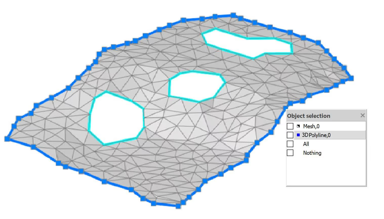
Added command NG_MESH_GET_BOUNDARY to extract the inner and outer boundaries of a surface as 3D polylines.
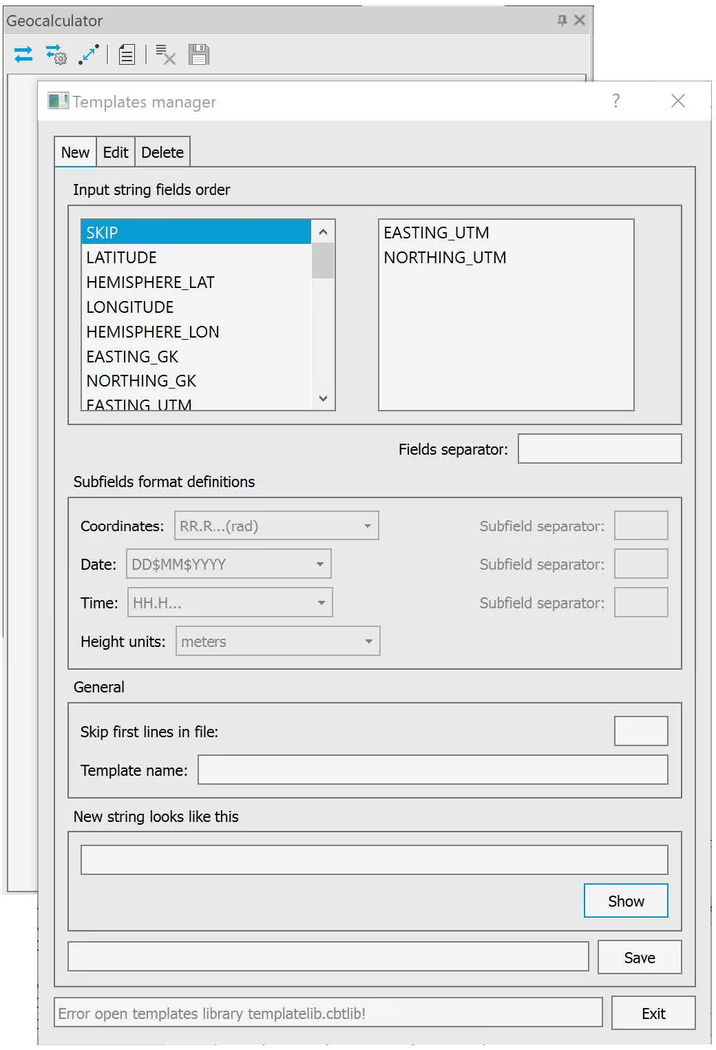
Geocalculator
The new Geocalculator (NG_GEOCALC) toolbar calculates:
- transformation parameters;
- distances and bearings on an ellipsoid or a plane;
- coordinate transformations between systems, including coordinates loaded from a text file.
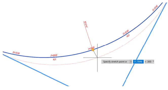
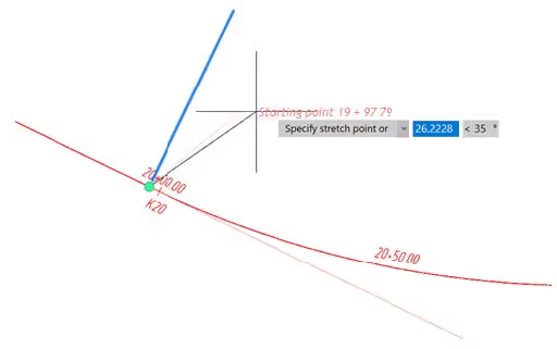
Route objects and labels
Route objects and labels now have grips for editing their geometry.
Updates and Improvements in the Topoplan Module
In the 3D slope command (NG_3D_SLOPE), slope hatching now follows changes of direction more accurately.
When map symbols are already selected, the symbol catalog now lets you choose whether to replace them or draw a new symbol.
Improvements to the commands for labeling contours (NG_CREATE_CONTOUR_LABEL) and downhill ticks (NG_CREATE_BERGSTRICH) let you place them automatically along a line. Choose the text style and height for contour labels, or a block for downhill ticks.
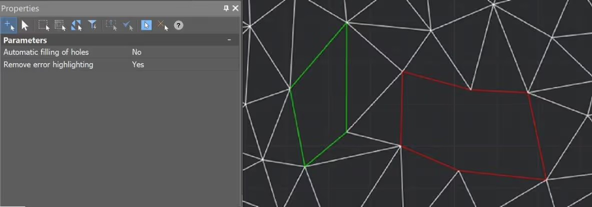
The new options in Fill Mesh Holes (NG_MESH_SEAL_HOLES) let you highlight detected holes and fill them automatically.
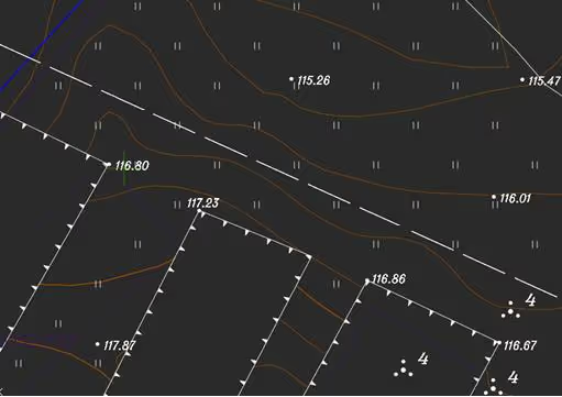
A new group in Map Symbols (NG_CLASSIFICATOR) supports custom map symbols for communication lines:
The selected face and edge now highlight when you add a surface point with (NG_MESH_VERTEX_ADD).
You can now name the output layer when creating contour lines with (NG_CREATE_CONTOUR_LINE).
The geopoint tool (NG_CREATE_POINTS) now also lets you create blocks manually.
Fixed errors in the breakline command (NG_MESH_STRUCTURAL_CREATE) and improved selection when adding multiple objects.
You can now include the start and end points when creating interpolated points with (NG_CREATE_POINTS_BY_INTERPOLATION).
When using NG_EXPLODE_POINTCLOUD on a cloud with more than 100,000 points, you can explode it into point objects only. For clouds with fewer than 100,000 points, geopoints and blocks are also available.
You can now add points beyond the existing surface boundary with Add Point (NG_MESH_VERTEX_ADD) and Add a Points Group (NG_MESH_VERTEX_ADD_BY_POINTS).