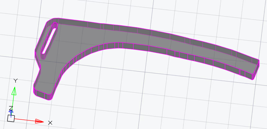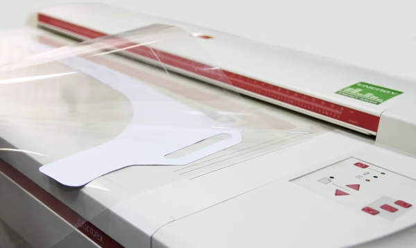
A CNC machine, laser cutter, or 3D printer may be available even when the original part has no CAD file. This example shows how to turn a scanned template or photograph into an editable DXF outline using automatic vectorization.
The starting point
The template is cut from white cardboard and was made by measuring a full-size sample. We need a DWG or DXF outline to send to a cutting plotter.
Prepare the scan
Choose a scanner that can accommodate the size and thickness of the template, or use a camera if the template is too large. For the large patterns in this example, a 300 dpi scan provides sufficient detail. Protect the template with a clear A2, A1, or A0 sleeve, or a sheet of transparent film for larger originals. Scan in grayscale.
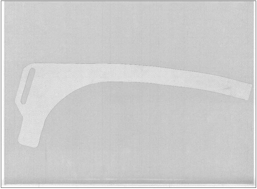
Prepare the scan
Use Insert Image to place the scan in nanoCAD Raster model space. Scale it so the dimensions in the drawing match the actual part.
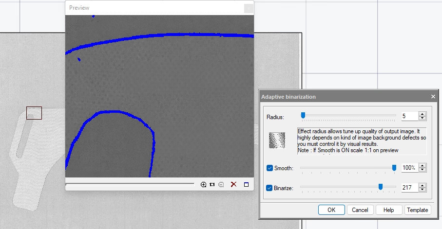
Use Adaptive Binarization to convert the grayscale image to black and white. Adjust the settings in the preview until the outline is continuous and as few stray pixels as possible remain.
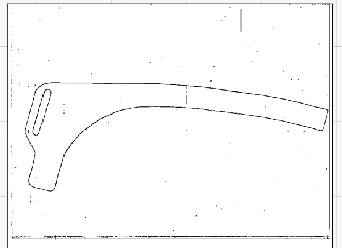
Use Crop by Rectangle to remove the unused part of the image. Then run Speckle Remover to remove isolated marks before tracing.
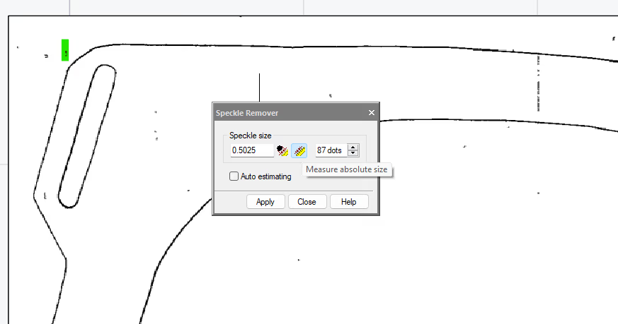
Use Measure Size to measure the largest speck you want the filter to remove.
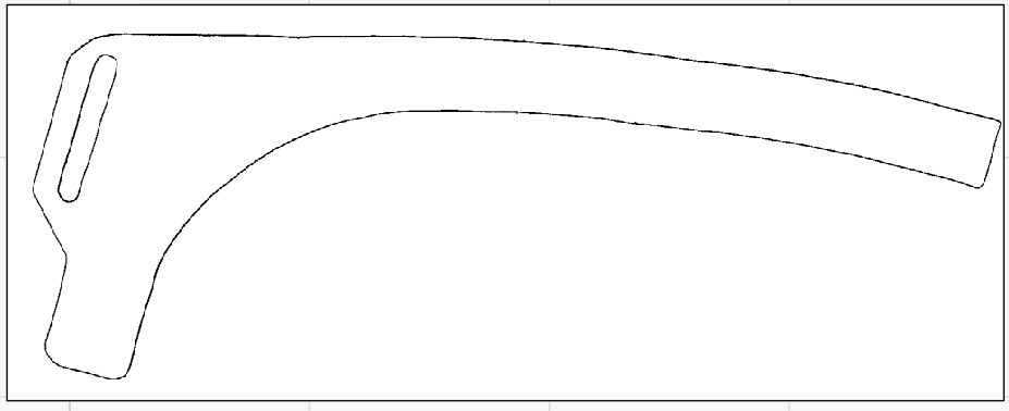
Vectorize the outline
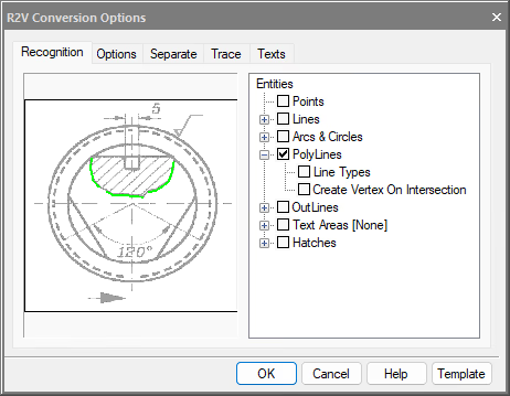
Open the R2V conversion options. On the Recognition tab, select the geometry you want the software to create. This template needs only polylines.
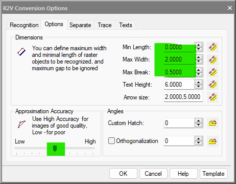
On the Options tab, set the tracing accuracy, line width, and maximum gap the vectorizer should bridge.
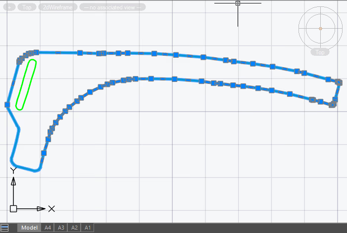
Run Raster to Vectors and compare the resulting outline with the scan. Remove the raster image from the drawing and save the vector geometry as a DXF file.
Conclusion
The scanned template or photograph now has an editable DXF outline for downstream CNC, laser cutting, or 3D printing workflows.
With nanoCAD Raster, you can do the image cleanup and tracing in the drawing itself.