Build a library of reusable blocks, attach attributes to them and turn the attribute values into a report.
A block groups drawing objects into a single reusable element. Draw a symbol once, then insert as many copies as the project requires.
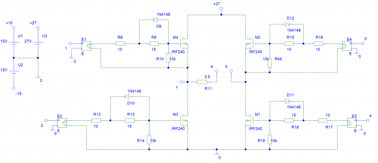
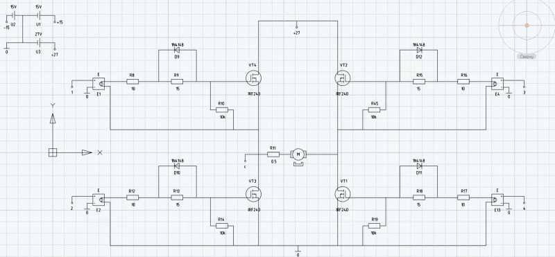
Many designers use a separate application for electrical schematics. Here we’ll build a block library in nanoCAD for an H-bridge circuit that controls a brushed DC motor.
The reference circuit contains repeated resistors, diodes and transistors. Each symbol has one or two text labels. Some labels vary between instances, such as resistor designators R1 and R2. Others, such as the diode type, can stay the same.
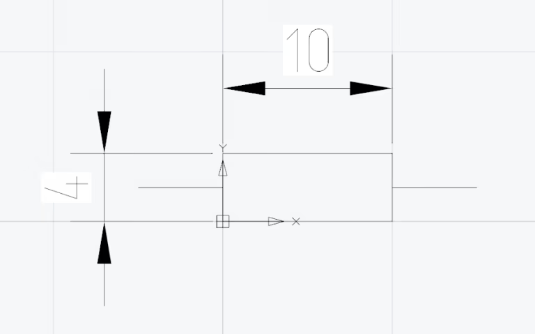
Start by drawing a resistor symbol to the dimensions shown in Figure 2.
Create a block
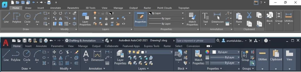
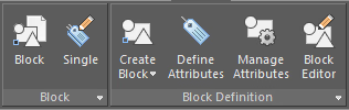
On the Insert tab, look for the Block and Block Definition panels (Fig. 3).
Select the resistor symbol and choose Create Block to open the Block Definition dialog (Fig. 4).
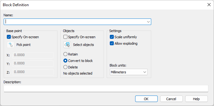
Select Scale uniformly and Allow exploding. Under Base point, select Specify on-screen, then click OK.
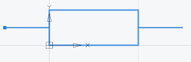
Choose the left lead as the insertion point (Fig. 5).
Each resistor needs two labels: its reference designator and its resistance value. Define them as block attributes so you can give each inserted instance different values while keeping the same symbol.
Define block attributes
Start with the resistor’s reference designator.
Run the attribute definition command (ATT) to open the Attribute Definition dialog.
Enter the attribute name, prompt and default value (Fig. 6).
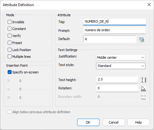
Set the text justification to Middle Center so the attribute sits in the center of the resistor symbol. Figure 7 shows the other options.
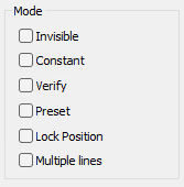
Leave the mode options unchecked in this example. The text should remain visible, its value should vary between resistors, and no extra verification or preset value is needed. We also use single-line text and leave its position unlocked.
Click OK and specify the attribute’s insertion point (Fig. 8).
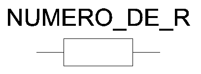
Create a second attribute for the resistance value. Next, add both attributes to the block definition.
Add the attributes to the block
Explode the resistor block back into drawing objects so you can include the designator and value in its definition.
Select the resistor geometry and both attributes, then run Create Block again.
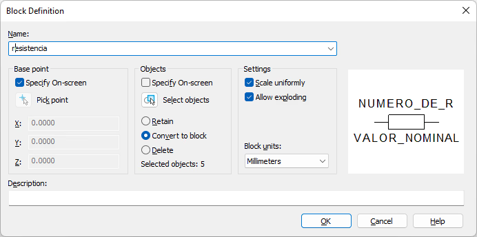
After you specify the insertion point, enter R8 as the designator and 10 Ω as the resistance. Click OK (Fig. 10).
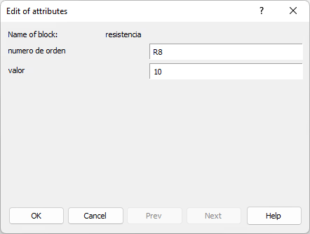
The resistor block now contains both attributes (Fig. 11).
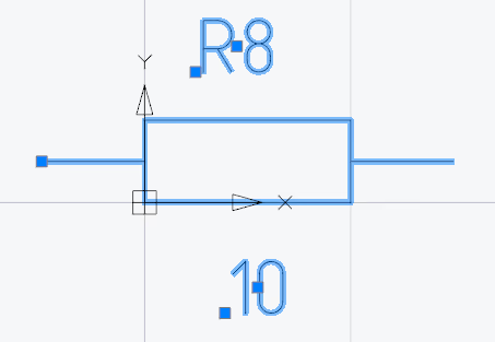
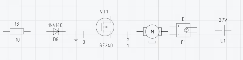
Define the remaining symbols and attributes in the same way until the library contains all the parts for the H-bridge (Fig. 12).
Insert the blocks
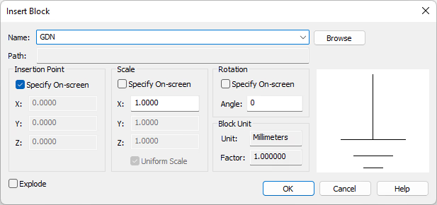
Insert the blocks to reproduce the H-bridge schematic. Figure 13 shows the Insert Block dialog.
Tool palettes
Add the blocks to a tool palette so they are available in other drawings without recreating them.
The palette files are stored in this folder:
%AppData%\Nanosoft\nanoCAD x64 21.0\ToolPalette
Add the blocks to a tool palette so they are available in other drawings without recreating them.
Run TOOLPALETTES to open the Tool Palettes window.
Right-click My Palettes to create a new tool set. Drag your blocks onto it (Fig. 14).
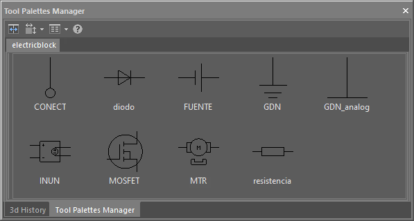
You can now assemble the circuit in model space and enter the attribute values for each symbol.
Remove unused blocks
Unused block definitions increase the file size. Run BLOCKS to see the block names and the number of references to each definition.
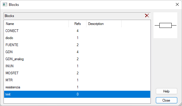
The test block has no references. Select it and click the delete button in the upper right.
Blocks can also contain hyperlinks, be written to disk or supply attribute data for reports such as bills of materials.
Enjoy the tutorials.