Scanners can introduce distortion, especially on large sheets. Calibration corrects nonlinear distortion in raster images, including scanned technical drawings, survey plans, and maps.
Calibrate the scan before editing or vectorizing it. Otherwise, tracing transfers the distortion to the vector drawing, where errors are much harder to correct.
The source document must contain points with known coordinates. Paper deformation or scanning errors can shift those points in the image. Calibration transforms the scan so that the measured positions match the known coordinates.
Four-point correction
If the original dimensions of a rectangular drawing border are known, use its four corners as control points for four-point correction.

The border corners are usually near the edges of the image and well separated, which helps constrain the correction across the whole sheet. Choose a standard sheet size from the list or enter the border dimensions manually. The command adjusts the entire image to bring the four scanned corners onto their reference positions.

Calibrating a map against its grid
This method suits map sheets, charts, and other cartographic scans that contain a coordinate grid or graticule.
In the calibration dialog, set the grid origin, direction of the horizontal axis, X and Y grid spacing, and the number of rows and columns. Pick the origin in the image, or enter its coordinates if the scan is already positioned in the user coordinate system.

The reference grid appears over the scan, revealing any displacement. Pick each corresponding grid intersection in the scan. The software records the displacement between each reference position and its measured position.

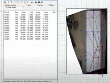
The Calibrate dialog lists the known and measured coordinates side by side. Use the error check to assess the fit. After calibration, corresponding grid intersections should coincide.
Combining a grid with additional control points
Some scans contain a grid over only part of the sheet. Where possible, add control points near the image edges. If you correct only the gridded region while the edges remain fixed, you may distort the rest of the image.

Extend vector construction lines through the outermost grid intersections to establish additional reference points. In the Calibration dialog, remove any unused grid nodes for which you have no matching point in the scan.
Aligning adjacent sheets
If Align cannot bring two scanned sheets into register, use Calibrate.

Align the sheets in the following order.
-
Scan the sheets with an overlap so they share recognizable features.
-
Extend the blank margins of the image you intend to adjust. Otherwise, Calibrate may clip it at its original boundary.
-
Set the image background to transparent if this makes it easier to see the overlap.
-
In the Calibration dialog, specify enough matching point pairs to align the overlapping areas accurately.
Calibrating against control points
You can also align two images or register a scanned image to vector geometry. Identify features common to both, such as building corners or intersections.
In the Calibration dialog, pair each known position in the target with its measured position in the scan. The number of pairs depends on how much distortion you need to correct and the accuracy you require.

For a large set of points, enter all the target positions first. Select them in the Calibrate dialog and choose Change Point. The command advances through the list as you pick the matching positions in the scan.

Check that the control points coincide after calibration. If an area is still misaligned, undo the result, add control points in that area, and calibrate again.
Conclusion
Distortion in a scan carries through to vectorized geometry and hybrid edits. Calibrating the raster first gives you a more reliable basis for tracing and measurement.