An artist can suggest volume and texture using little more than the direction and spacing of strokes. A CAD hatch pattern works on much the same principle.
In a drawing, different patterns help us distinguish materials and surfaces. They can also be used for illustration.
Choose a hatch scale that suits the detail. A pattern that looks clear on a broad surface may become too dense in a small area.
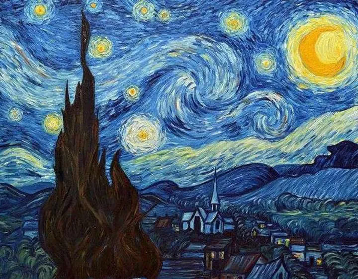
Let’s recreate Vincent van Gogh’s The Starry Night in nanoCAD. A closer look at the painting reveals contours and textures we can represent with CAD geometry.
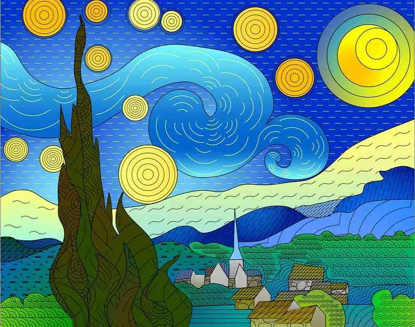
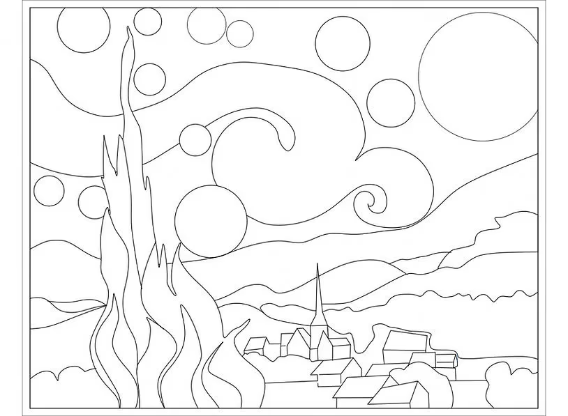
Copy the image (Ctrl+C) and paste it into model space (Ctrl+V). Trace the main contours with SPLINE and CIRCLE. Follow the shapes loosely, as you would in a sketch. You can even hatch an open contour.
The outlines in Figure 3 will form the base of the illustration.
Choose Home → Draw → Hatch, or type HATCH at the command line. The dialog has two tabs, Hatch and Gradient.
Click the right-pointing arrow in the lower-right corner of the dialog to see the additional settings.
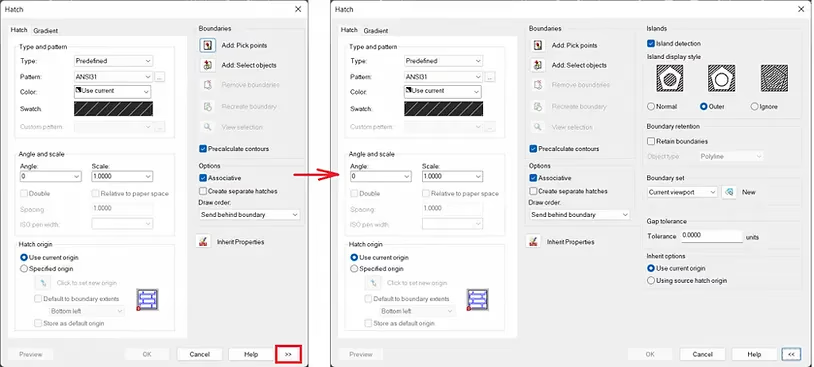
Start with a pattern from the built-in library. Choose it from the list, or click the ellipsis or the pattern swatch to open Hatch Patterns. In nanoCAD 22, the SHX folder under C:\ProgramData\Nanosoft\nanoCAD x64 22.0 stores both shape files (.shx) and hatch patterns (.pat). You can add your own files there. Restart nanoCAD after adding a file.
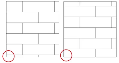
To control where the pattern starts, pick a hatch origin (Fig. 5). Save it as the default origin to set the HPORIGIN system variable.
In the Boundaries section, use the top button, Pick points, to select the area to fill. Enable Precalculate contours if you want to preview a possible boundary as you move the pointer.
Make the hatch associative if you want it to follow changes to its boundary.
For an open boundary, set a gap tolerance from 0 to 5,000 drawing units. Gaps within the tolerance are treated as closed.
The Gradient tab offers several fill styles. Figure 6 shows how they look.
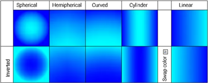
Fill the image with gradients, then overlay the hatch patterns. Leave the moon empty for now. We’ll create a custom shape for it.
[1] A shape is a predefined graphic stored in an SHX file, much like a character in an SHX font.
With the contours in place, FASTHATCHCMD and FASTGRADIENTCMD let you reuse the previous hatch or gradient settings.
Figure 7 shows the gradient fills so far, with their color numbers in parentheses.
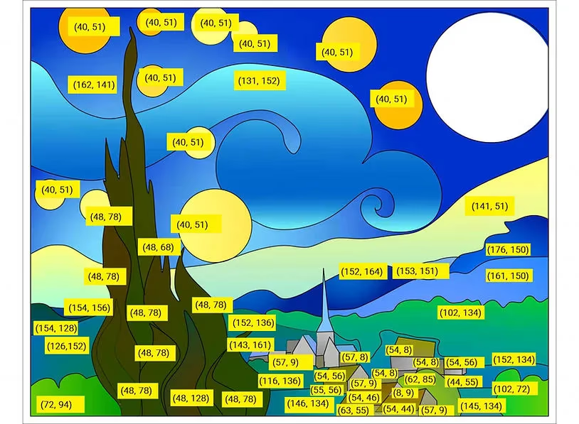
Next, we’ll design a hatch pattern of our own.
Hatch definitions are stored in .pat files. You can open them in a text editor, and one file can contain several patterns.
Most of the illustration uses patterns from nanoCAD’s library. For the roofs, we’ll make a new pattern so you can see how a custom hatch works.
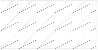
There are two ways to define a hatch pattern.
1. Draw the pattern
In nanoCAD Construction, you can turn drawn geometry into a hatch pattern with SPHPATTERN.
-
Draw a square boundary no larger than 300 × 300 mm, with its lower-left corner at the origin.
-
Draw one repeat of the pattern with LINE. Approximate curved portions using straight segments.
-
Assign a color to each segment.
-
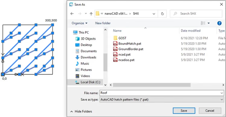
Repeat the geometry in a square array of at least nine elements so the program can recognize the pattern. Keep continuous lines unbroken. In Figure 9, the red segment repeats in three rows and three columns, with 100 mm spacing in each direction. The five blue segments are copies, trimmed or extended to the sketch boundary.
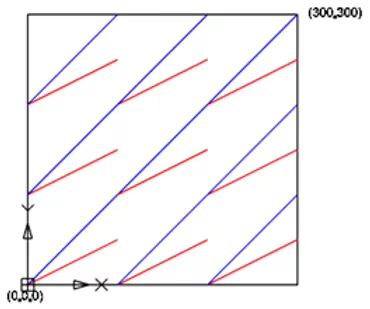
Line up each segment with its corresponding segment in the next repeat. They must be parallel and in the same row.
Select the pattern elements and run SPHPATTERN. Choose Save As and select a folder (Fig. 10).
2. Write the pattern in a text editor
Start the pattern definition with an asterisk, followed by a unique pattern name, a comma and a short description.
Each subsequent line of the file defines one family of line segments. Enter the values in the order shown in Table 1, separated by commas.
Table 1. Pattern line definition
-
Angle of the line family relative to the world X axis (α)
-
X and Y coordinates of the origin in the WCS
-
Offset along the local X axis
-
Offset along the local Y axis
-
Dash length
-
Gap length, entered as a negative number
For the roof pattern, start the .pat file with the pattern name and a description, then enter the repeating line definitions.
Start with the red line. Place its origin at (0, 0) in the world coordinate system (WCS). Each repeat occupies a square with a side length b of 100 mm (Fig. 11).
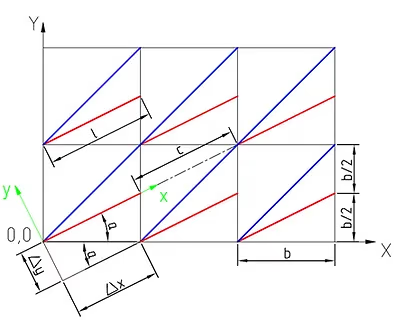
Enter the angle α from the world X axis to four decimal places, followed by the origin coordinates (0, 0). For the offsets, use the line’s local coordinate system. Its X axis runs along the segment and its Y axis is perpendicular. In Figure 11, the repeat to the right has offsets Δx = b × cos α and Δy = b × sin α. The remaining values are the dash length l and the gap c before the next dash on the same line.
Repeat the calculation for the blue line. Since it is continuous, omit the dash and gap lengths. Figure 12 shows the result.

Apply the new pattern to the roofs and choose existing hatches for the surrounding areas (Fig. 13).
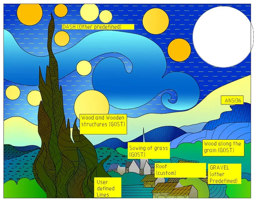
Both methods give us a repeating line pattern. Some details in the painting call for individual shapes or solid fills. We’ll use shapes for those next.
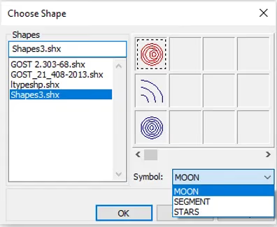
Choose Home → Draw → SHAPE to open Choose Shape. The built-in shape libraries include GOST 2.303-68.shx, GOST_21_408-2013.shx and ltypeshp.shx.
We’ll add a few shapes of our own (Fig. 14).
Define the shape in a plain-text .shp file and compile it into an .shx file. In nanoCAD 22, place the compiled file in C:\ProgramData\Nanosoft\nanoCAD x64 22.0\SHX to use the shapes in your drawings.
Each shape definition has a header followed by its specification bytes.
-
*shape_number,byte_count,NAME
-
byte1, byte2, ..., byte N − 1, 0 (N ≤ 2000)
Each shape number must be unique within its .shp file. The specification bytes describe the vectors that make up the shape.
A vector code has three characters. The leading 0 marks a hexadecimal value. The second character gives the length in drawing units, from 1 through F (15). The third gives the direction shown in Figure 15.
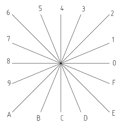
Special codes let you draw additional geometry, including arcs. Table 2 lists the ones we’ll use here.
Table 2. Special shape codes
0
End shape
Ends the current shape.
001
Pen down (draw)
The pen starts down at the beginning of each shape. In this mode, each vector draws a line.
002
Pen up (move without drawing)
With the pen up, a vector moves the pen to a new position without leaving a mark.
003
Divide the vector length by the next byte
Use scaling for fractional vector lengths, such as 0.5, or when the required length exceeds F (15).
004
Multiply the vector length by the next byte
Scale factors accumulate. Multiplying by 2 and then by 5 scales subsequent vectors by 10. Reverse the scaling at the end of the shape to restore the initial scale.
008
X/Y offset, specified by the following two bytes
A standard vector code allows 16 directions and a maximum length of 15 units (F). Code 8 lets you specify an X/Y displacement instead. Follow it with the two offsets, in the order 008, X offset, Y offset.
Each offset can range from −128 to +127. Parentheses can make the pair easier to read.
After this displacement, drawing resumes in standard vector mode.
009
Multiple vector displacements
Use code 9 for a sequence of arbitrary X/Y offsets. The example below draws three vectors before returning to standard vector mode.
009, (2.5), (7,1), (4, -5), (0,0)
End the sequence with the pair (0, 0) to return to normal vector mode.
00A
Octant arc (two specification bytes)
An octant arc spans one or more 45-degree sectors. It begins and ends on an octant boundary. Octants are numbered counterclockwise.
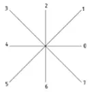
10, (radius, ±0SC). The first byte (10) is the arc code.
The second byte gives the radius, from 1 to 255.
In the last byte, the sign gives the direction, positive for counterclockwise and negative for clockwise. S identifies the starting octant (0–7). C gives the number of octants covered (0–7), with 0 representing all eight, a full circle. Parentheses are optional.
00С
Arc defined by X/Y displacement and bulge
Follow code 00C with the X offset, the Y offset and the bulge value, in that order.
The X and Y displacements and the bulge can each range from −127 to +127.
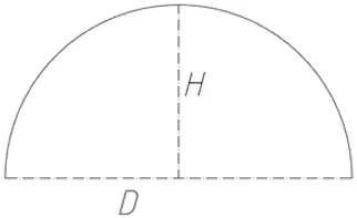
The bulge is k = (2D/H) × 127. Use a negative value for a clockwise arc.
00B
Fractional arc (five specification bytes)
00B, (start_offset, end_offset, high_radius, low_radius, ±0SC)
The start and end offsets tell you how far each endpoint lies from an octant boundary. The high byte of the radius is zero for radii up to 255. For larger radii, multiply the high byte by 256 and add the low byte. Interpret the final octant byte as for code 00A.
For the start offset, find the angle in degrees between the starting octant boundary (a multiple of 45 degrees) and the start of the arc. Multiply by 256 and divide by 45.
Calculate the end offset the same way, using the angular distance from the end of the arc to the corresponding octant boundary.
An endpoint exactly on an octant boundary has an offset of zero.
00C
Multiple arcs defined by bulge
Enter a triplet for each arc segment, then end the sequence with an offset of (0, 0).
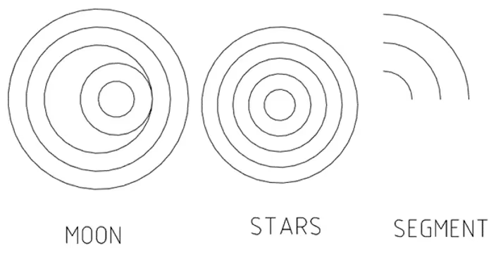
We can now use these codes to draw the shapes in Figure 16.
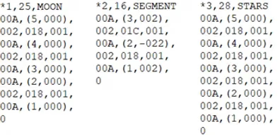
All three shapes are in Shapes3.shx. Put it in the SHX folder to make the shapes available in the Choose Shape dialog (Fig. 17).
When you share a DWG that uses custom shapes, include its SHX files. ETRANSMIT can package them with the drawing.
Inserting a shape is much like inserting a block. Choose the size and rotation when you place it. You can also repeat a shape across an area with Home → Draw → FillShapes. These fills are nonassociative. Above the horizon, we’ll use the LUNA shape from GOST 2.303-68.shx.
Once LUNA is in place, give each circle of the moon its own gradient. Make it brighter toward the center and darker at the edges.
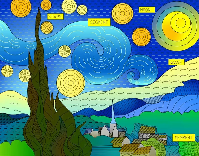
In this drawing of The Starry Night, we’ve used nanoCAD 22 to
-
apply hatches and gradients,
-
insert shapes from SHX files,
-
fill an area with a shape,
-
locate and share hatch and shape files, and
-
create custom patterns and shapes.
Enjoy experimenting with your own drawings.

The_Starry_Night_by_nanoCAD.zip
Download ZIP (551 KB)