Parametric design takes a different approach from conventional drafting. By capturing the relationships behind a part’s geometry, a designer can revise it more quickly and consistently. This has helped make parametric modeling an established design practice.
The nanoCAD Mechanica standard parts library contains parametric components. Parameters control the geometry of each part, and relationships between parts reflect the standards that govern their dimensions and fit.
MechWizard can link dimensions within a part and across parts in the library. One definition can therefore produce several variants of a part or control how the components in an assembly fit together.
This tutorial shows how to build a parametric library part and constrain it to other components in an assembly.
Part 1. Prepare the geometry
Use standard nanoCAD drawing tools to create the part from simple geometric primitives, or import an existing DWG drawing from another CAD system (Figure 1).
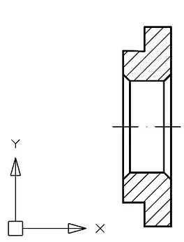
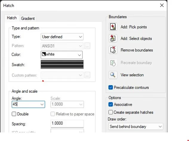
When hatching the part, set Type to User Defined. This allows MechWizard to recognize the hatch when you create the parametric library object (Figure 2).
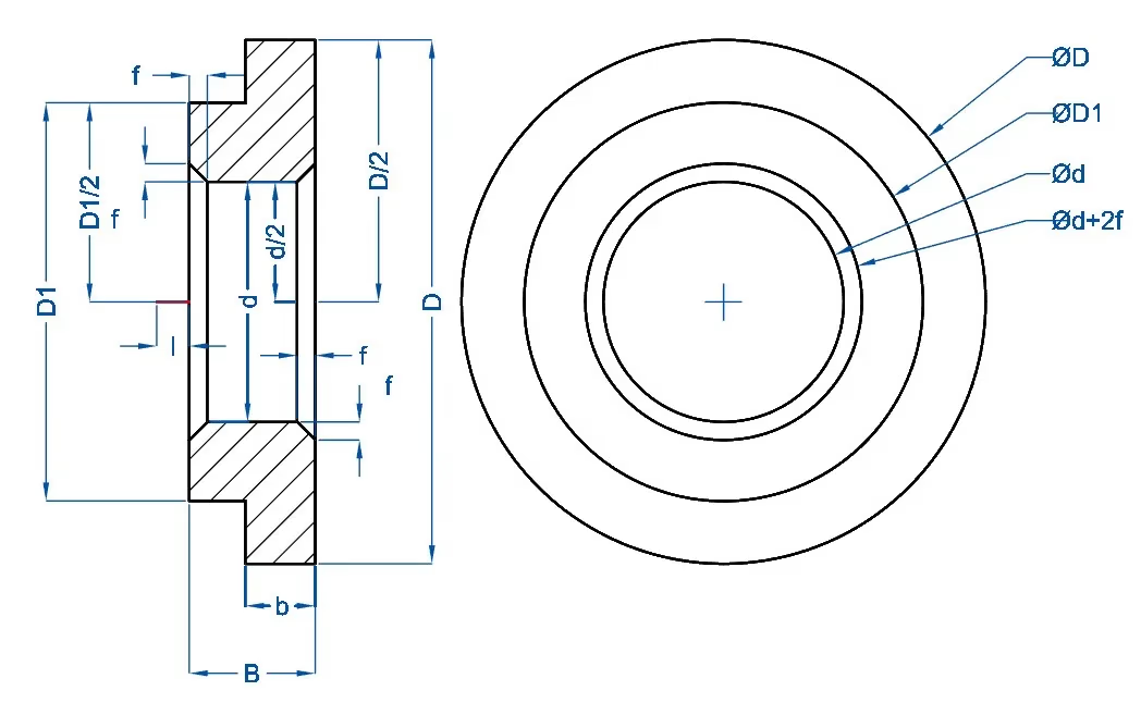
Draw the second view and label the dimensions with letters (Figure 3). Use the same letter for the same dimension in both views.
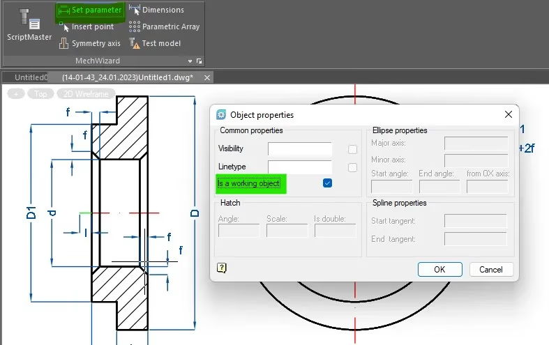
The dimension labeled l in the first view defines the insertion point. Draw an auxiliary line segment, choose Set Parameter in MechWizard, select the segment, and press Enter. In Object Properties, enable Work Object and click OK (Figure 4).
Add the part to the library
With the geometry drawn and dimensioned, open MechWizard with the mcsmaster command to create the library object.
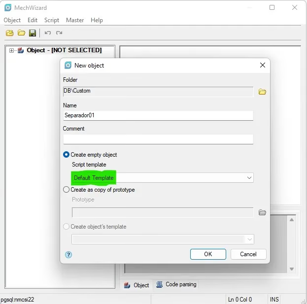
Choose Object → New Object. Select a library folder (Custom in this example), enter the part name, and click OK (Figure 5).
To add geometry, right-click the Implementation branch in the Object Wizard and choose Add Implementation. Right-click in the wizard workspace to create a second view (Figure 6).
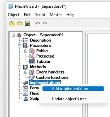
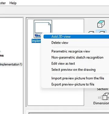
Assign Front View to the first view and Side View to the second.
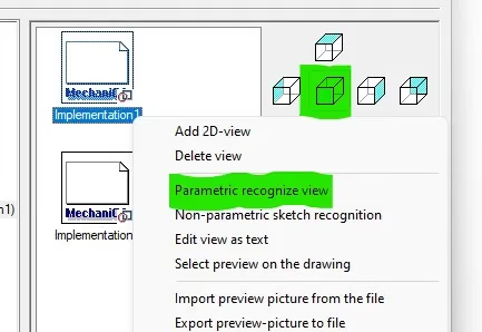
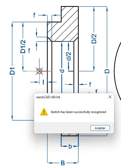
Associate each view with the corresponding drawing. Select the view, choose Parametric Recognize View, and select its geometry. For the insertion point, pick the left endpoint of the segment dimensioned l. MechWizard confirms when recognition is complete (Figure 7).
The object script
Open the Script branch in the object tree. The workspace shows the default functions that describe the part (Figure 8).
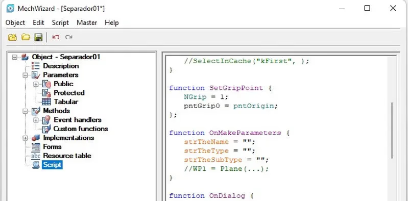
The library now contains a part with geometry assigned to its views.
Next, use the Script Wizard and a similar library part to define the parameters.
Part 2. Edit the part script
The new part has a basic script but no variables. A similar library part provides a starting point for defining its behavior.
Add parameters to the part
Download the sample library object to use as the source of the script.

shaiba.zip
Download ZIP · 468 KB

In the parts library, select the Custom folder and choose Import (Figure 9). Browse to the downloaded file and click Open to add the object to the library.
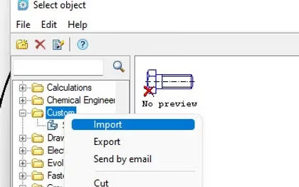
Open the Script menu for your part and choose the option to copy a script from another object. In the part selection dialog, select the object you just imported (Figure 10).
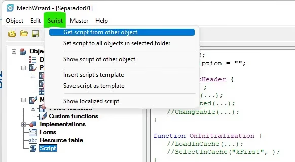
The sample part has simpler geometry. To adapt its script, open the Master menu in MechWizard and choose Script Wizard. You’ll add parameters and set their initial values.
Fill in the basic properties as shown in Figure 11.
In Part List Entry, enter the name that should appear in the bill of materials.
Cover Order determines which object appears in front where parts overlap in an assembly view.
Click Next.
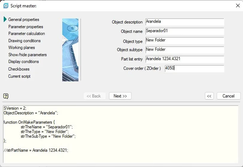
In Parameter Properties, enter the following values for this example.
b = 4; B = 6; D = 71.5; D1 = 0.75*D; d = 30; f = 1; l = 0
To make a parameter editable, select it and enable the editing option. Repeat for each parameter you want users to change (Figure 12).
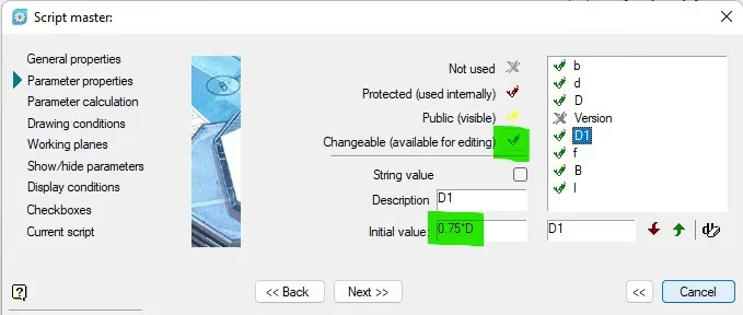
Check the parameter order. D must appear before D1 because the formula for D1 uses D. Use the ordering buttons to move a parameter if needed.
Click Next twice to leave the following two screens at their defaults.
Add a work plane so the part can be constrained to other components. Choose Add Plane, set its orientation to OYZ, and make the plane available for editing by other objects (Figure 13). Click Next.
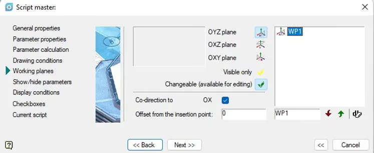
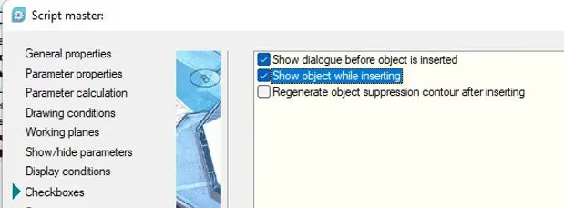
Continue through the next two screens. In the Checkboxes window, enable the option to show the object during insertion.
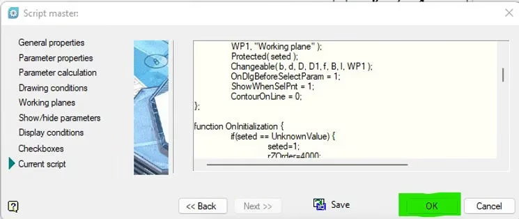
The final screen shows the generated script. You can return to an earlier screen to adjust the settings. Click OK and save the script (Figure 14).
Save the part and close the wizard.
Test the parametric part
Select the part in the Custom folder and move the pointer into model space. Pick the insertion point and direction. In the dialog, edit a parameter in the Value field or select a view on the left to preview it.
Set B to 4 and b to 2, then click OK. The washer changes shape to match the new dimensions (Figure 15).
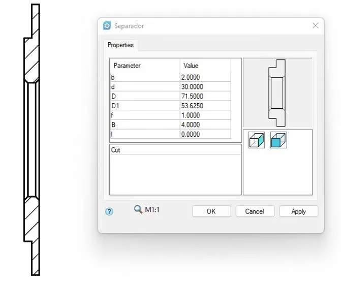
Double-click the washer to edit its dimensions later. That works for occasional adjustments, but a designer may need more than a dozen washer sizes. Store frequently used sizes as named variants so you can select them without re-entering dimensions. The next section also shows how to constrain a washer to adjacent parts.
Part 3. Create part variants and assembly constraints
A single library object can hold several part variants. When you also define relationships to other library components, changes to their parameters can update the assembly.
You’ll now add a second washer variant and define how the washer fits the bearing and shaft.
Add a part variant
Open the washer in MechWizard. Under Implementation, choose Add Implementation and create a view as before. Run parametric recognition on the new variant using the same sketch as the first variant. One view is enough for this example (Figure 16).
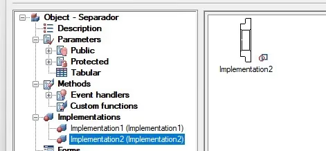
Edit the object script
With the geometry assigned to the second variant, update the script to supply its dimensions.
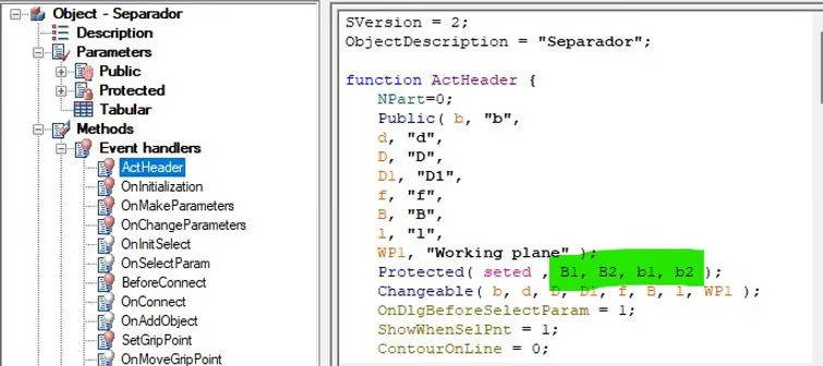
Expand Methods → Event Handlers to find ActHeader, OnInitialization, OnMakeParameters, and OnDialog. In the Protected section of ActHeader, declare seted, B1, B2, b1, and b2 (Figure 16).
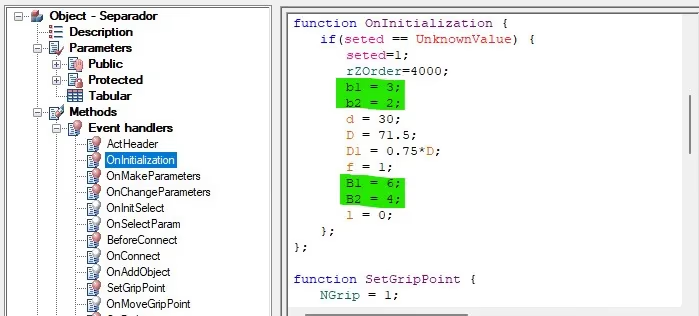
In OnInitialization, replace the original B and b values with B1 = 6, B2 = 4, b1 = 3, and b2 = 2 (Figure 17).
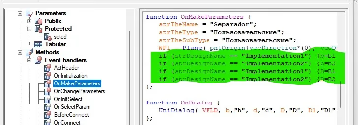
In OnMakeParameters, add the following assignments so each variant receives its own dimensions (Figure 18).
if (strDesignName == "Implementation1") {b=b1};
if (strDesignName == "Implementation2") {b=b2};
if (strDesignName == "Implementation1") {B=B1};
if (strDesignName == "Implementation2") {B=B2};
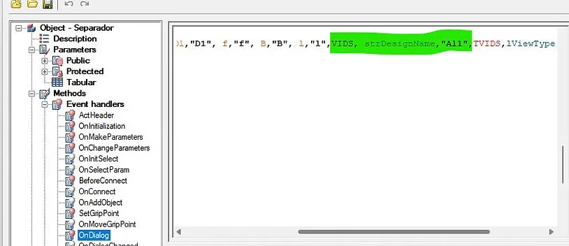
To list both variants in the Insert dialog, add VIDS, strDesignName, "All" to OnDialog (Figure 19).
UniDialog(VFLD, b,"b", d,"d", D,"D", D1,"D1", f,"f", B,"B", l,"l",VIDS, strDesignName,"All",TVIDS,lViewType,"All",VIEW,"Vids");};
Save your changes and close the Object Wizard. Insert the revised washer from the library into model space. The properties dialog now offers two variants (Figure 20).
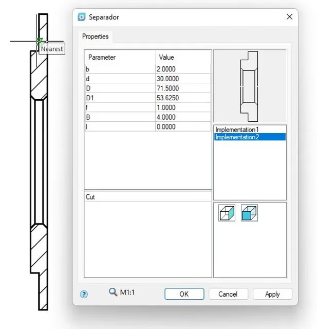
Select the second variant and click OK. The washer width changes to the values you set in OnInitialization.
Constrain the part to other components
To use the washer in a parametric assembly, define its relationships to other parts in the OnConnect handler.
Reuse the supplied sample script, or copy the relevant code from a library part that behaves the way you need.
Open the spacer washer in MechWizard and paste the sections for OnConnect and OnSelectParam.
function OnConnect{ if (rPart == 0 ) {
if(obj.strTheName=="SimpleBearing"){
rNearest = findNearest(pntOrigin, obj.WP,1,2);
if(rNearest == 1){
SetGeomConstraint(INSERT, CONTRDIRECT, obj, WP1, obj.WP1, 0);
} else {
SetGeomConstraint(INSERT, CONTRDIRECT, obj, WP1, obj.WP2, 0);
}
}
} if (rPart == 1 ) {
if(obj.strTheType == "Arbor" && obj.strTheSubType == "Round"){
if(obj.strTheName == "StdSegment"){
SetParamConstraint(d, obj, EXPR, "obj.rDiameter", FALSE);
NoVectorSelect = 1;
Handled = OBJ_HANDLED;
}
}
}
if(obj.strTheName == "StdSegment"){
SetParamConstraint(d, obj, EXPR, "obj.rDiameter", TRUE);
rNearest = findNearest(pntOrigin, obj.WP,1,2);
if(rNearest == 1){
SetGeomConstraint(INSERT, CODIRECT, obj, WP1, obj.WP1, 0);
} else {
SetGeomConstraint(INSERT, CODIRECT, obj, WP1, obj.WP2, 0);
}
} }function OnSelectParam {if (rPart==0) {
l=rXcoord;
}
}
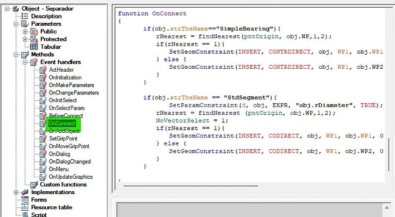
The first part of the script constrains the washer to a bearing. Selecting the bearing aligns the washer face with the corresponding bearing plane. The side you pick determines whether the washer faces left or right.
The second part constrains the washer bore, represented by d, to the diameter of the selected shaft segment.
Open BeforeConnect to add a prompt that tells the user what to select when placing the washer. Insert the following expression immediately after ResetLastConstraint(); in the handler.
if(rPart == 0) {strPromt = "Select a bearing or shaft step"; }
Set NSelect to 2 in ActHeader to request two selections when the part is inserted. After selecting the bearing, the user can select a shaft segment to set the washer bore diameter.
Finally, update OnChangeParameters so the washer retains the correct orientation when its parameters change.
function OnChangeParameters {
b = new.b;
d = new.d;
D = new.D;
f = new.f;
B = new.B;
l = new.l;
D1 = new.D1;if(IsFixedParam(WP1)){
fix = 1;
pntOrigin = Point(new.WP1);
vecDirection = -Vector(new.WP1);
}
Handled = OBJ_HANDLED;
};
Save your changes and close the Object Wizard.
Add a preview image
You can use an image or a 3D model for the preview. In the Object Wizard, select the top node in the object tree and choose the appropriate preview option from its context menu.
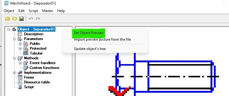
For the 3D washer model in this example, choose Set Object Preview.
Arandela3d.dwg
Download DWG · 363 KB
Open the drawing containing the model in model space. Select the geometry and press Enter. The washer appears in the preview pane. Save your changes and close MechWizard.
Test the washer in an assembly
Use the sample assembly of standard Mechanica components to check how the new object behaves.
Ejeconbalero.zip
Download ZIP · 64 KB
Open the assembly and select the spacer from the Custom folder in the parts library. The BeforeConnect prompt appears, followed by the command line prompt for an insertion point. Pick the bearing on the side that places the washer to its left (Figure 22).
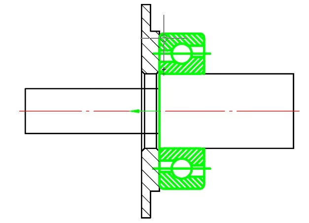
Click to place the washer. For the second selection, pick the shaft segment the washer will fit. This sets the bore diameter. In the Insert dialog, you can edit parameters, switch views, or choose another variant. Select the second variant and click Apply. The washer width changes while the bearing and shaft constraints remain in place (Figure 23).
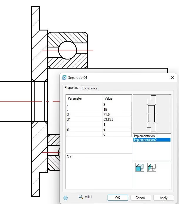
Click OK to accept the change. To choose another variant later, double-click the washer to reopen the Insert dialog.
The shaft, bearing, and washer are now linked parametrically. Changing a driving dimension, such as the shaft diameter, updates the parts that depend on it.
Conclusion
You prepared dimensioned geometry, created a library part, imported an existing object, and used its script as a starting point. You then defined part variants in the Script Wizard and added assembly constraints.
The initial setup takes more work than drafting a single washer. Once the relationships are in place, the same object can cover multiple sizes and respond to assembly changes.
As parametric models become more common in mechanical design, tools for building and maintaining them have become an important part of nanoCAD Mechanica’s development.