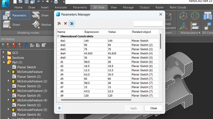
Parameter Manager
Define dimensions and relationships in one table. When a value changes, linked features update the model.
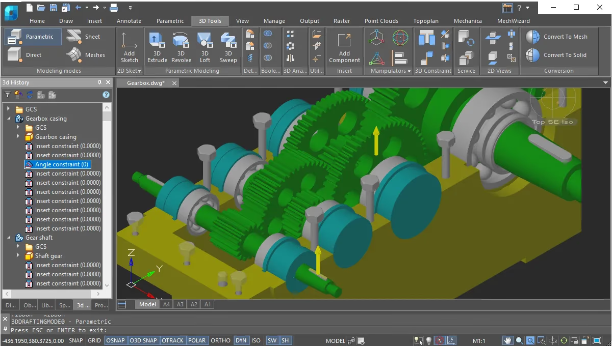
nanoCAD Platform + 3D Modeling
Model solids, control parameters, build assemblies, and produce drawings in the same DWG environment.
Build solids from dimensioned sketches or edit model faces directly as the design evolves.
Work with direct modeling, parametric features, sheet metal, and meshes, then generate 2D drawings in the same application.
Integrated tools
Create, edit, constrain, and exchange 3D models within nanoCAD Platform.
Define dimensions and relationships in one table. When a value changes, linked features update the model.
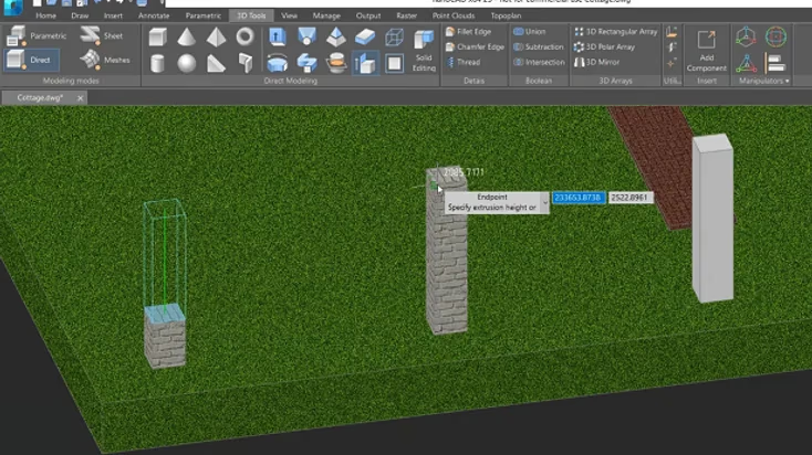
Move a face until it aligns with existing geometry to modify a solid without rebuilding it.
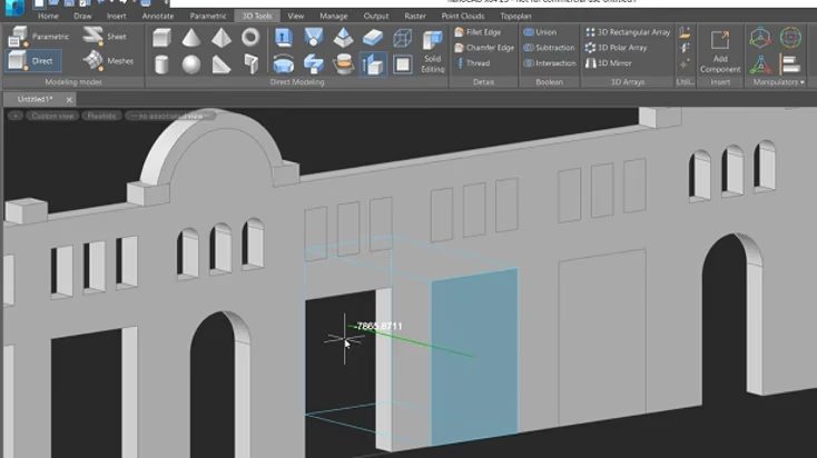
Turn a closed profile into a solid or cutout by setting the extrusion height on the model.
Switch between parametric, direct, sheet metal, and mesh modeling. The ribbon shows the commands for the selected mode.
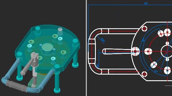
Generate 2D views from the model. Projected views and their documentation update when the geometry changes.
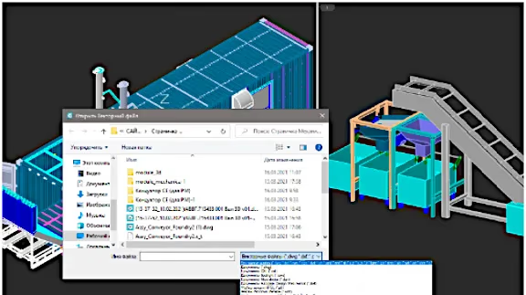
Import and export common engineering formats, including STEP, IGES, Parasolid, SAT, C3D, STL, JT, and VRML.
Isolate a project area or reveal internal geometry by temporarily hiding objects outside a selected volume.
Link parts stored in separate files and receive notifications when a collaborator changes a referenced component.
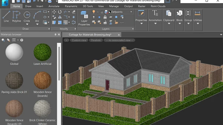
Apply materials and visual styles to review the model’s appearance and present the design.
Also included
Additional tools for fabricating parts, documenting models, and working with complex projects.
Build folded parts, add standard sheet metal features, and generate flat patterns for fabrication.
Inspect the modeling sequence, return to an earlier stage, and edit individual features without rebuilding the part.
Manage complex assemblies with separate parts, 3D constraints, and external references.
Detect geometric relationships as you draw to define parametric profiles with fewer manual constraints.
Combine, subtract, and intersect bodies. Add fillets, chamfers, shells, and construction geometry.
Temporarily align the work plane with a face to draw or edit geometry without setting the axes manually.
Make a part translucent as you move or rotate it to see where it fits within the assembly.
Open 3D scan data in common formats and use it as a reference alongside solids and other drawing objects.