Adapted from an article by (y)lab. Read the original in English at https://www.ylab.ca/2d_laser_update/.
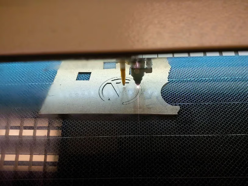
We’re updating our class materials for 2D CAD and laser cutting for three reasons.
-
DraftSight is no longer free. It’s good value, but the cost matters to our hobbyist members.
-
Our laser cutter started handling drawings differently. We haven’t worked out whether the change came from the software or the machine, but the cutter still works.
-
We’ve learned a few things about how our cutter software handles drawings, and we’d like to pass them on.
The scale of a hatch matters. A pattern that looks clear at full size can crowd a small detail. We wanted to see what nanoCAD offered.
Why we chose nanoCAD Free for 2D drafting and laser cutting
Other CAD programs we tried
We tried several 2D CAD programs as possible replacements for DraftSight.
We originally chose DraftSight because its command line felt familiar to AutoCAD users. It takes a little practice to learn that way of drawing, but it pays off in speed and accuracy.
Most 2D CAD comparison sites we found offered short product descriptions. Few showed what the programs were actually like to use.
Here’s how the programs compared for our particular mix of 2D drafting and laser cutting.
LibreCAD. Free, open source and unrelated to LibreOffice. We liked it, although we ran into bugs and saw little development in the three years leading up to our review. It was a promising program that could have used more developers.
FreeCAD. A powerful choice for 3D, with plenty of tutorials and an active development community. You can give dimensions names and define other dimensions with formulas. For our 2D laser-cutting classes, though, the interface was a bigger change from AutoCAD than we wanted.
QCAD was worth a look. We’d seen regular releases and real improvements over three years. The command line differed from AutoCAD’s, and QCAD supported the full set of Microsoft fonts. At the time, the free edition supported DXF. Pro was a one-time CAD $50 purchase with a year of updates. It added support for formats including DWG and SVG and could turn text and drawings into outlines. A separate CAM module offered a free trial and could generate G-code for CNC machines.
Autodesk Fusion 360. We could download it for free, but the interface took some getting used to. Like FreeCAD, it made more sense to us for 3D work than for our 2D classes. Coming to it expecting AutoCAD would do a very different program a disservice.
nanoCAD. Of the free programs we tried, nanoCAD came closest to the AutoCAD workflow we already knew. Some of its 3D features could also be useful for CNC work. At the time of our review, the paid edition used an annual subscription and was evolving faster than the free edition.
Which CAD program suited our workshop?
We chose nanoCAD because we wanted a free program that felt familiar to DraftSight and AutoCAD users. For someone who works with a lot of text, images or different file formats, we thought QCAD Pro was worth the CAD $50. Its trial let us try the vector conversion tools before buying. We still had to test how well those worked for CNC.
The rest of this guide describes our experience with nanoCAD.
nanoCAD editions and features
By the time of our review, nanoCAD had become a dependable 2D drafting program with an active user community. The Help menu pointed us to the support forums and a YouTube channel with plenty of tutorials.
Like DraftSight in its early days, nanoCAD offered a free edition alongside a paid annual subscription.
When we wrote the original review in April 2022, nanoCAD Free was still available as version 5. It had stopped following the commercial release cycle, and the website described it as an older version.
Moving from AutoCAD to nanoCAD Free
Working at the command line
The command line follows a familiar pattern. Type a command at the bottom of the screen, then respond to its prompts. If you use it regularly, you’ll notice small differences between programs.
One difference we noticed was arithmetic. In AutoCAD and DraftSight, we could enter 225/533 as a scale factor to resize 533 mm to 225 mm. In the version of nanoCAD Free we tested, we worked it out on a calculator or in a spreadsheet first.
In the free version we tested, drawing a 10 × 10 rectangle from (0, 0) worked a little differently. Enter the dimensions, then move the mouse into the quadrant where you want the rectangle.
Icons and layout
The icons look different, but most of the tools are in familiar places. Hover over a button to see its name.
Opening and saving DXF directly
In our AutoCAD and DraftSight workflow, we saved the drawing as a DWG and exported a DXF for the laser cutter.
nanoCAD Free let us open and save both DWG and DXF directly. Its default AutoCAD 2013 DXF format worked with our laser cutter and CNC machines.
Open a drawing first
On startup, nanoCAD Free looks ready to draw, but a command can fail if no drawing is open.
Start with File → Open or File → New.
Working with grid snap and object snaps
Some people like SNAP, which aligns points to a grid whether or not you can see it. It’s not for me. Then again, some people prefer corn syrup to real maple syrup on their pancakes.
I leave SNAP off on the status bar. If you use it, turning GRID on lets you see where the points will land.
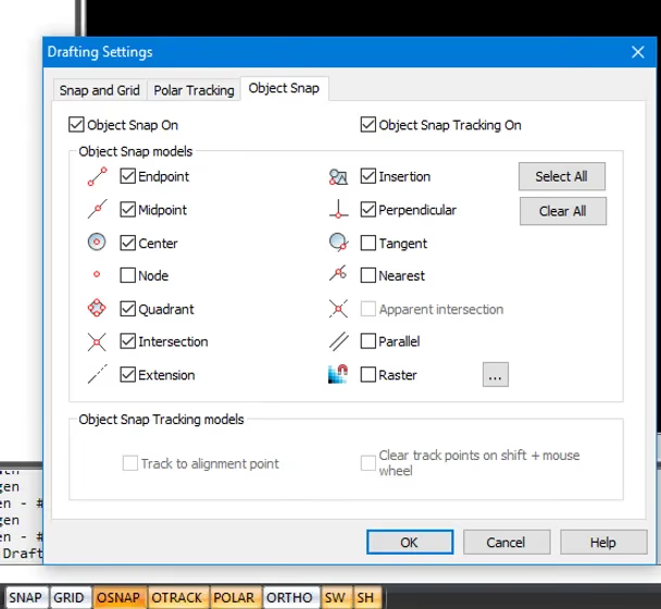
I do use object snaps (OSNAP). They let me pick an exact endpoint, intersection or center without guessing.
Right-click a status bar button for its options. For object snaps, open Drawing Settings at the bottom of the menu to choose exactly which snaps to enable.
Three other status bar controls we use
-
ORTHO constrains lines to the horizontal or vertical.
-
POLAR helps you draw at selected angles, such as 45 degrees.
-
OTRACK shows temporary alignment paths from object snap points, including paths at your polar tracking angles.
Preparing a drawing for the laser cutter
A few checks in the CAD drawing can save you time when you open it in the cutter software.
Check the drawing origin
The drawing origin (0, 0) corresponds to the corner of the grid in our cutter software.
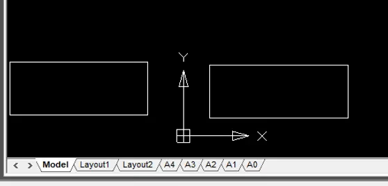
We’ve had users import a drawing and think it was empty.
In the illustration, the rectangle on the right falls inside the cutter grid. The one on the left falls outside it. Check where your geometry sits if an import seems to disappear.
Check the dimensions
Our cutter’s grid matches the machine bed, 900 mm (about 3 ft) along X and 600 mm (about 2 ft) along Y.
Check the dimensions before saving. A drawing imported at the wrong scale can be far larger or smaller than you expect.
Use dimension lines
The default dimension text was too small for us to read comfortably in AutoCAD, DraftSight and nanoCAD. In nanoCAD you can change its size directly from the dimension.
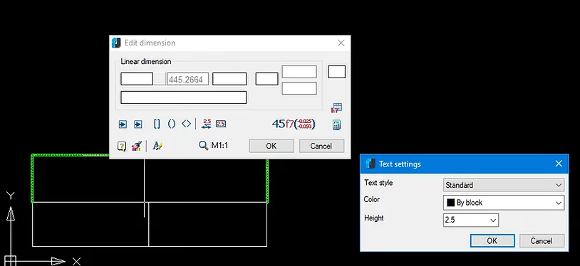
Right-click the dimension line to open Edit Dimension. In our example the value is 445.2664. Click Text Style, third from the left on the bottom row, to set a more readable text size.
Remove overlapping lines
Two adjacent rectangles can share an edge and leave two lines on top of each other. A laser cutter or mill will follow that edge twice.
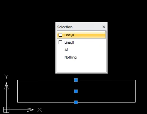
After exploding the objects in nanoCAD, click the overlapping line. You can see both elements and delete the one you don’t need.
Converting text and images to vectors
If text or an image disappears when you import a drawing into the cutter software, check what kind of object it is.
-
The nanoCAD Free version we tested doesn’t vectorize text or images.
-
Our cutter ignores ordinary text and raster images.
-
Convert text and images to vector outlines before opening them in the cutter software.
You can still use ordinary CAD text while working out the layout and dimensions. Keep two copies of the drawing.
-
Save the editable original under a name such as myfile_raw_text.dxf.
-
Save the converted drawing under another name, such as myfile_vectorized.dxf.
We sometimes set the text in a word processor for a wider choice of fonts and effects, including text on a curve.
Converting the lettering or artwork
-
Start with large lettering in your word processor, at least 28 points. Some fonts change shape at smaller sizes. A larger sample gives the converter more detail, and we’ve seen smaller lettering produce unwanted intersecting lines.
-
Take a screenshot of the lettering. Check that the cursor or other stray marks haven’t crept into the image.
-
Use a converter such as Convertio or Vectorization.org to make a DXF.
-
Open the DXF in a new tab. If you see nothing, zoom out. The imported outline may extend beyond the visible area.
-
Use SCALE to resize the outline before copying it into the drawing.
Do not use red in your drawings
This one caught several of our users.
Our laser software highlights problem lines and vectors in red.
Keeping the drawing itself in another color makes those warnings easy to see.
Remove stray geometry
Remove stray marks, even a single isolated pixel. They can cause errors in the cutter software.
Engraving along a vector path
If you only need an engraved outline, the drawing can stay as a line.
-
Use a lower power setting that does not cut the material.
-
Give engraving a different color from the cut layer.
-
Run the engraving pass first.
-
We’re putting together a settings chart.
Preparing filled areas for CNC
For a filled area, our laser software scans the design one row at a time from bottom to top, starting and stopping the beam as it crosses the boundaries.
For a CNC pocket, the software needs to know which area to remove. We mark it with a fill.
-
Draw the outline.
-
Hatch the enclosed areas.
Set Type to Custom.
On the Other Predefined tab, select SOLID.
Under Add, click Select Objects.
When the dialog closes, select the objects to fill and press Enter.
For an outline with a visible width, such as a ring, use two boundaries.
-
For a ring, use OFFSET to create the inner circle.
-
Repeat the fill operation with both circles selected.
-
Alternatively, adjust the object’s lineweight. This option has limits.
The controls at the bottom adjust fill and line thickness.
Set the object’s Thickness property to add depth. We haven’t tested this with the CNC machine.
-
Viewing depth in 3D
-
Choose View → Visual Style → 3D Wireframe, then View → Orbit to rotate the view.
-
To return to 2D, choose Views → Plan View → Current UCS.
Checking the drawing for errors
-
Use a color other than red for drawing geometry so you can spot the software’s warnings.
-
Look for pairs of small squares at line ends. They flag intersections and open contours. Zoom in if they’re hard to see.
-
Select one checkbox at a time to see each kind of error separately.
-
Increase the fill size to close any gaps.
-
Use object snaps to join line endpoints accurately.
Test the material
We’ve found that material properties can vary between batches, particularly with MDF.
Try a simple cut and engraving on a sample of the material. Adjust the settings as needed. For a smaller test, scale down your drawing and use a scrap piece.


