Standard parts library
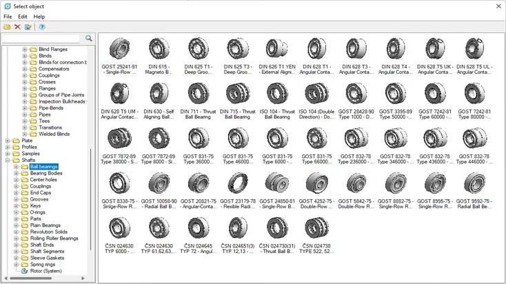
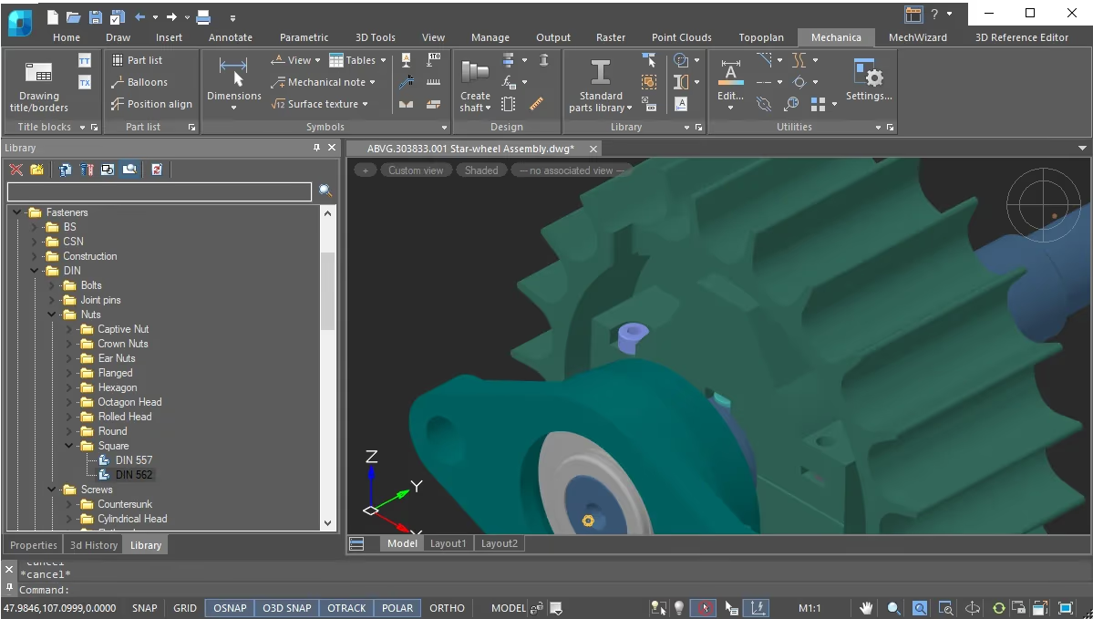
Find and insert fasteners, structural sections, bearings, gears, motors, gear reducers, and piping components in 2D or 3D.
nanoCAD Platform + 3D Modeling + Mechanica
Design parts and assemblies, insert standard components, run engineering calculations, and prepare mechanical drawings.
Combine DWG drafting and 3D modeling with a library of standard parts and parametric components for mechanical design.
Keep calculations, drafting standards, and bills of materials in the same project to reduce manual work.
Specialized tools
Insert components, design mechanisms, and produce manufacturing documentation from the design.
Find and insert fasteners, structural sections, bearings, gears, motors, gear reducers, and piping components in 2D or 3D.
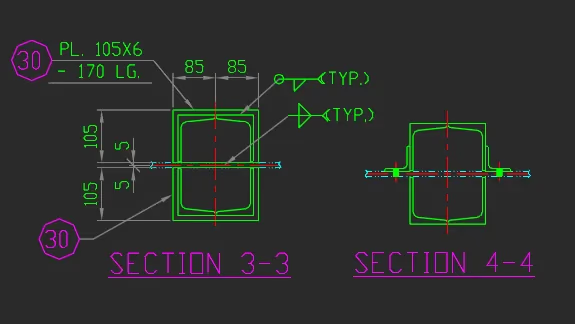
Create views, sections, dimensions, engineering symbols, tables, and multi-sheet drawings with dedicated mechanical drafting commands.
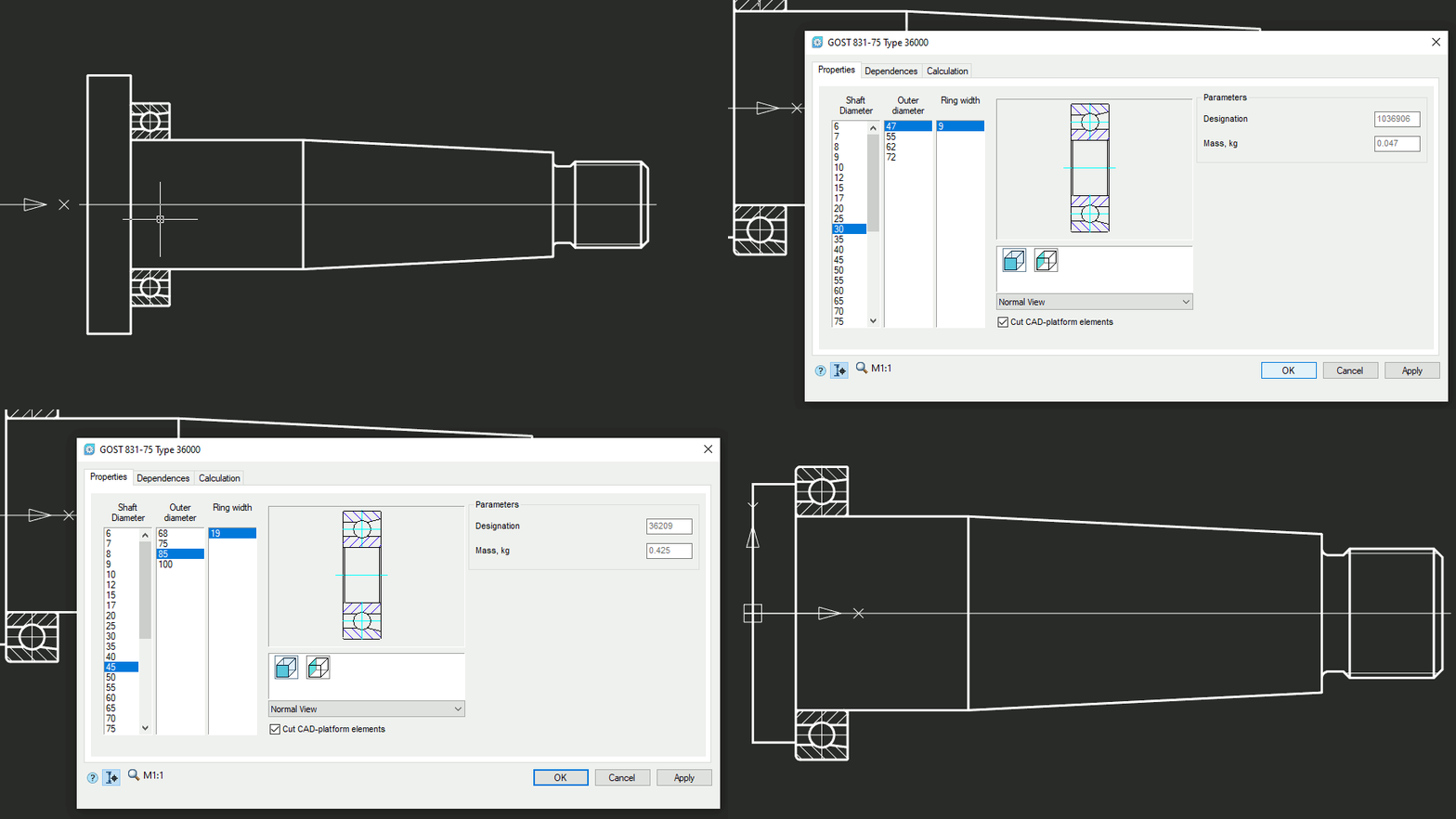
Change a part’s dimensions and update related drawing components using values from the database.
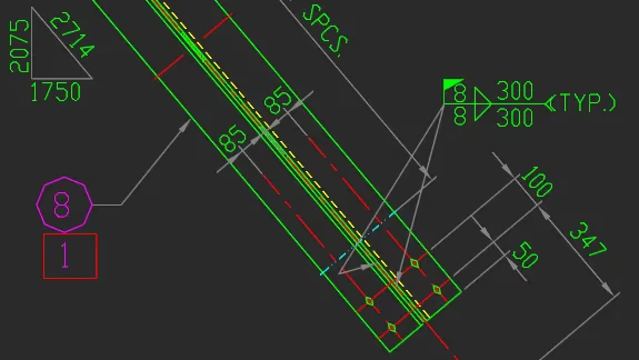
Apply styles, tolerances, fits, surface finish symbols, technical notes, and sheet formats based on international standards.
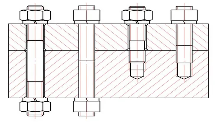
Size bolts, screws, studs, or rivets to suit the thickness of the parts and create fastener patterns.
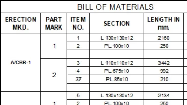
Generate parts lists from the drawing and update item numbers, quantities, and part data as the design changes.
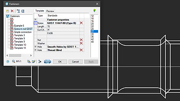
Calculate gear and fastener parameters and bearing life, then produce reports with formulas and ISO references.
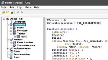
Define dependencies between objects and specify how standard parts behave, or create your own parametric components.
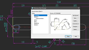
Control arrowheads, text position, and tolerances with dimension styles for different drafting standards.
Also included
Additional tools for standardizing drawings, sizing components, and keeping project data current.
Create enlarged details that retain their scale and update when the original geometry changes.
Build shafts, pipe runs, and related components with dedicated tools and editable component data.
Organize assembly documentation across several sheets while keeping drawings, views, and project data together.
Define plate dimensions, control bends with parameters, and include the finished parts in the bill of materials.
Add fits, deviations, surface finish and weld symbols, markings, and other manufacturing annotations.
Build tables from drawing objects and refresh them when the underlying data changes.
Insert standard flanges, gaskets, and pipe connections in 2D or 3D.
Select set screws, pins, and other fasteners from the library by the required standard.